Troubleshooting
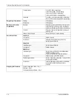
IFL cable runs of 400 to 670 feet (123 to 206 m) require the following cable specifications:
Cable type:
RG-35
Impedance: 75
ohm
DC resistance:
1.15 ohm per 1000 feet
Shield:
Single shield, solid
Shield coverage:
100%
Capacitance:
15.4 picofarads per foot
Jacket: Standard
PVC
Maximum loss:
2.69 dB per 100 feet at 1500 MHz
Outside diameter:
0.63 in over jacket
Weight: 0.14
lbs/ft
IDU connector:
N (male), F (male) available with adapter
ODU connector:
N (male), F (male) available with adapter
Only N and UHF-type connectors are available. An N-to-F adapter must be used. An N-to-F adapter is Tiernan
part number 31-0121-032 or Gilbert Engineering's NS-5504-1.
RG-35 cable is provided by Andrew Corporation (Andrew part number: LDF4-75A). The N plug (male) 50 ohm pin
is Andrew part number: L4NM-7550, reference L44W-75.
LNB DC voltage drop should be less than 3 V, regardless of length, cable type, LNB type, or data rate.
IFL Cable Preparation
This section assumes an RG-11 coaxial cable is being used in the installation. For any other cable type, the
procedures remain the same with only the dimensions changing. Before connecting the coaxial cable, prepare it
by attaching the F connectors as described here and as illustrated in Figure C-1:
1.
Remove 3/4 inch (9.55 mm) of the cable jacket, being careful not to cut through the braid. Fold the first
layer of exposed braid back over the jacket.
2.
Cut through the remaining foil, braid, and dielectric to expose 1/4 inch of center conductor. Do not score
the center conductor.
3.
Remove the first foil, making sure the braid is not cut, and fold the second braid over the jacket.
4.
Cut through the foil and dielectric to the center conductor an additional 3/8 inch. Do not score the center
conductor.
5.
Insert the connector over the foil and dielectric until it bottoms.
6.
Crimp the collar using a .470 to .475 hex crimp tool, as shown in Figure C-1.
Use the following steps to complete the connection of the coaxial cable:
1.
Cut off approximately two inches of weatherproof, heat-shrink tubing (Alpha Part Number FIT-650-3/4, or
equivalent) and place it over the end of the coax cable. When installation is complete, this is used to
provide a weatherproof shroud for the outdoor IFL connector, up to the body of the LNB downconverter.
2.
Connect the IFL coax cable to the coaxial cable connector.
3.
Slide the heat-shrink tubing over the coaxial connector and male F connector on the LNB downconverter
so it completely envelops the threaded portion. Apply heat to the heat-shrink tubing in accordance with
the manufacturer's instructions.
Tiernan DBR3000
Page
B-3
Summary of Contents for DBR3000
Page 2: ...Overview Page 1 2 Tiernan DBR3000 ...
Page 6: ...Warranty Policy Page vi Tiernan DBR3000 ...
Page 10: ...Preface Page x Tiernan DBR3000 ...
Page 14: ...Safety Precautions Page xiv Tiernan DBR3000 ...
Page 64: ......
Page 73: ...Troubleshooting Figure C 1 Coax Cable and F Connector Assembly Tiernan DBR3000 Page B 5 ...


