8
01-0868-401B 12/02
Installing the TDR60
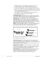
Cabling the ASI IN
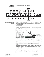
The ASI IN port accepts the incoming ASI transport stream, with data rates up to
104 Mbps, on a female BNC connector, 75
Ω
impedance.
Cabling Video
Outputs
The composite analog and digital video is output from BNC ports.
Analog
The composite analog video out connector, J10 COMP, provides composite
analog video output on a female BNC 75
Ω
, 1 Vpp nominal, 0.7 minimum,
1.4 maximum.
Digital
The digital video out connector, J11 D1, provides serial digital video output on a
female BNC 75
Ω
connector.
Cabling Audio
Outputs
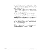
The TDR60 provides up to four analog audio outputs using male XLR connectors
and two AES/EBU stereo outputs using BNC connectors.
Analog
The analog audio connectors are as follows:
■
J6 A Right is a baseband, analog audio, right channel output on an XLR 50W
male connector. The balanced analog stereo clips at +18dBu.
■
J7 A Left is a baseband, analog audio, left channel output on an XLR 50W
male connector. The balanced analog stereo clips at +18dBu.
■
J8 B Right is a baseband, analog audio right channel output on an XLR 50W
male connector. The balanced analog stereo clips at +18dBu.
■
J9 B Left is a baseband, analog audio, left channel output on an XLR 50W
male connector.The balanced analog stereo clips at +18dBu.
Connector
.
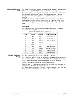
A diagram of the XLR connector is shown at
the right.
The connector pinout is shown in the following
table:
Digital
The digital audio connectors are as follows:
■
J12 AES/EBU A is a baseband, stereo audio, output on a BNC 75 W
connector. The unbalanced digital stereo clips at +18 dBu.
■
J13 AES/EBU is a baseband, stereo audio, output on a BNC 75 W connector.
The unbalanced digital stereo clips at +18 dBu.
XLR Pin Assignments
Pin
Description
1
Ground
2
Positive Signal (+)
3
Negative Signal (-)
XLR Male
3
1
2


