background image

52

01-0868-401B 12/02

Troubleshooting

Remote Unit Problems

Problem:

No sign-on message on the remote terminal after power-up.

Solutions:

Verify that the cable between the terminal and the TDR60 are properly connected.

Ensure that the remote unit and the TDR60 are turned on and plugged into an active AC 
outlet.

Verify that the baud rate and parity of the remote unit communications package match the 
DVB setting of the TDR60 remote control interface. DVB settings are 9600 baud, 8 data bits, 
no parity, and 1 stop bit.

Teletext Problems

Problem:

No teletext or teletext incorrectly displayed.

Solutions: Ensure that VBI Format is set to OFF and that VBI Teletext Mode is set to ON — 

when VBI Format is set to On, teletext will not display correctly.

Video Problems

Problem:

No video output

Solutions:

Ensure that the TDR60 is powered up and has been initialized.

Ensure that the TDR60 and the video monitor are powered up and properly connected.

Verify that the Eb/N

0

 level meets minimum requirements for link operations.

Verify that the Status LED is illuminated. If the Status LED is not illuminated, follow the steps 
for Troubleshooting Loss Of Sync.

Ensure that the video cabling to the encoder at the uplink is properly connected.

Ensure that the associated encoder is configured for the video input source that is being 
provided.

Problem:

Jerky or freeze frame video output

Solutions: Verify that the aggregate data rate does not exceed the transport clock rate. If 

necessary, increase the encoder transport clock rate, or reduce the encoder 
compressed video bit rate.

Problem:

No video or audio output

Solutions:

Ensure that the encoder, the TDR60, and the audio and video monitors are powered up and 
have been initialized.

Ensure that the cabling from the TDR60 to the audio and video monitors are properly 
connected.

Ensure that the video and audio cabling to the encoder at the uplink is properly connected.

Ensure that the polarity of the satellite downlink transport data between the encoder and the 
modulator is set correctly.

Ensure that the stream PID values for the encoder and the TDR60 match.

Verify that the E

b

/N

0

 level meets minimum requirements for link operations.

Verify that the Status LED is illuminated, indicating that the demodulator, decoder, and 
transport stream are all locked. If the Status LED is not illuminated, follow the steps for 
Troubleshooting Loss Of Sync.

Ensure that the service selected is the service you want to receive.

Video and Audio Sync Problems

Problem:

Video output does not sync with audio

Solutions: Adjust the video delay slightly. Changing the video delay may cause audio 

instability if not properly adjusted.

Summary of Contents for TDR60

Page 1: ...6340 Sequence Drive San Diego California 92121 4356 phone 858 458 1800 fax 858 657 5400 part 01 0868 401 B 12 02 TDR60 MPEG DVB Receiver Decoder Installation and Operation Guide...

Page 2: ...ercial Computer Software Restricted Rights JUNE 1987 clause at FAR 52 227 19 as applicable Manufacturer is Tiernan Radyne ComStream Inc 6340 Sequence Drive San Diego CA 92121 USA Contents of this manu...

Page 3: ...IN 8 Cabling Video Outputs 8 Cabling Audio Outputs 8 Cabling Data Outputs 9 Cabling a Remote Unit 10 Cabling the Fault Relay 10 Chapter 3 Using the Front Panel 11 Front Panel Components 11 Menu Struc...

Page 4: ...Margin Information 53 Maintenance 54 Appendix A Technical Specifications 55 Appendix B Factory Defaults 57 Appendix C QPSK Demodulator Application Notes 59 Configuration 59 Information Rate Symbol Rat...

Page 5: ...rm an operation with the TDR60 or if you do not use the TDR60 according to instructions The caution icon identifies information that requires careful attention in order to prevent equipment damage and...

Page 6: ...guide these values and messages appear in a different type date 06 23 2003 restore user1 Revision History This guide is periodically updated and revised For documentation updates call Tiernan Customer...

Page 7: ...ed the product shipment Other Tiernan Products The Tiernan Web site found at www tiernan com provides information about the entire line of Tiernan products and systems including encoders integrated re...

Page 8: ...e green yellow wire must be connected to the plug terminal marked by the letter E or by the earth symbol or color coded green and yellow The blue wire must be connected to the plug terminal marked wit...

Page 9: ...electric shock or fire There are no user serviceable parts inside the TDR60 If an object falls into the equipment unplug the unit and contact Tiernan Customer Service as serious damage could occur to...

Page 10: ...viii 01 0868 401B 12 02 Preface...

Page 11: ...ransport streams that are received from terrestrial networks and to perform valuable system confidence monitoring and troubleshooting functions Features The TDR60 features include Fully DVB and MPEG 2...

Page 12: ...rvice decoding ASI Input The TDR60 is highly versatile it can be easily configured to decode an MPEG transport stream from an ASI input instead of the satellite receiver input enabling the TDR60 to be...

Page 13: ...your operating parameters All configuration and monitoring functions can be efficiently performed using the front panel At a glance system status can be quickly determined by checking the front panel...

Page 14: ...4 01 0868 401B 12 02 TDR60 Overview...

Page 15: ...s to the rear panel and provide adequate ventilation To properly install the TDR60 follow the instructions provided in the appendix on table top and rack mount installation instructions Ventilation Th...

Page 16: ...nal AC power conditioning surge suppressor 5 Connect the AC power conditioning surge suppressor to an AC outlet Corrupted AC input power can interrupt operations and cause damage to the unit You shoul...

Page 17: ...e TDR60 For optimum performance the signal strength at the TDR60 should not fall below 65 dBm If the measured signal strength at the TDR60 is less than 65 dBm you may need to reduce the IFL cable loss...

Page 18: ...o right channel output on an XLR 50W male connector The balanced analog stereo clips at 18dBu J7 A Left is a baseband analog audio left channel output on an XLR 50W male connector The balanced analog...

Page 19: ...e shown in the table below Synchronous The synchronous data can be configured at rates up to 2 Mbps The connector J5 SYNC Data is an RS 449 DB 15 female connector The pinouts are shown in the table be...

Page 20: ...following table Cabling the Fault Relay The Fault Relay port J3 FLT RLY is a DB 9 male connector The fault relay is used in a redundant configuration A Tiernan redundancy switch monitors the output o...

Page 21: ...tion and messages Previous button used to scroll up to a previous menu level Next button used to scroll within the current menu level or to scroll forward through a list of parameters Selection button...

Page 22: ...ort Video Gain Chroma U Chroma V Delay Language Mode System PGCA VBI Data Rate Status Access Status Authorization Timeout on loss Teletext PID Mode Active Line Configs Save Restore Volume Language Mod...

Page 23: ...that the TDR60 is processing information When the asterisk disappears the process is complete Equal Sign Most parameters though not all can be modified in order to configure the TDR60 Configurable pa...

Page 24: ...t Panel Navigation Buttons The following front panel buttons are used to move through menus in order to issue commands and view status and fault information Next Button The Next button can be used whe...

Page 25: ...Selection buttons are used to select the menu item or parameter option displayed on the LCD To select the displayed item you press the Select button located directly below it The Select button perform...

Page 26: ...modified using the Selection buttons The parameter and its option will begin to flash 3 Change the parameter option as required If the available options appear in a list scroll through the list using...

Page 27: ...gin to flash 2 Change the parameter option to the correct value 3 Issue the parameter again by pressing the Enter button Example The following example describes how to move through menus and select op...

Page 28: ...the TDR60 you must enter an LO frequency that is the difference between the satellite downlink RF frequency and the TDR60 RF input frequency range Typically the LO frequency required is provided by t...

Page 29: ...Only available when Input Config Input Type Demod estimated Eb N0 level of received signal in dB Offset Query only displays a measurement in KHz of the difference between the actual satellite downlin...

Page 30: ...while the Auto Select function is set to On the TDR60 automatically changes the Auto Select function to Off Note If you change the Auto Select function to On after you have selected a service the TDR6...

Page 31: ...e for analog audio output The TDR60 cannot increase or amplify the incoming audio level If the volume is set to 18 dBu the output volume equals that of the input signal level If you set the audio volu...

Page 32: ...e No the service originator has not authorized the TDR60 to receive the selected service Timeout on loss Query only displays the amount of time in seconds that the service originator allows the TDR60...

Page 33: ...dix on VBI data transmission ATSCCC Detect Query only displays if ATSC closed captions are detected in the incoming stream No ATSC closed captions are not detected in the incoming stream Yes ATSC clos...

Page 34: ...e TDR60 to the last saved configuration set When a reset is performed the TDR60 reloads all programmable logic and firmware restarts the unit and clears the fault history log Press Enter to reset Rese...

Page 35: ...omatically saves any configuration changes performed using the front panel Whenever the power is turned on or the unit is reset the TDR60 restores to the last configuration you set Setting the Date To...

Page 36: ...s unlocked the front panel the LCD displays State Normal indicating that the front panel is unlocked If the wrong password is entered the TDR60 displays Password 0 If this occurs use the front panel k...

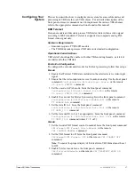
Page 37: ...ngs when the unit is reset or powered up Configuring Remote Software Parameters After you have cabled the remote unit to the TDR60 remote port perform the following steps to establish remote communica...

Page 38: ...to perform a specified action such as changing a configuration parameter Query commands direct the TDR60 to display the current setting of a specific parameter or to display current status informatio...

Page 39: ...command mnemonic is MC RS232 followed by a space The command instruction is BAUD followed by a space The parameter is 1200 Query commands are issued by typing the command without a parameter and press...

Page 40: ...attempt the command again If you are unable to execute the command contact Tiernan Customer Service Format Error The command syntax was entered incorrectly Re enter the command using the proper synta...

Page 41: ...es that stream to both the audio right and audio left outputs Stereo Supplies both mono streams to the audio left and right outputs exactly as sent by the encoder Front panel equivalent Audio Audiox M...

Page 42: ...rol Front panel equivalent None MC ACCESS CODE 1000 to 9999 7384 Sets the password required to unlock the front panel Front panel equivalent None MC ACCESS FP RO RW RW Sets the state of the front pane...

Page 43: ...2 1 Sets the stop bits for the remote port Front panel equivalent Control RS232 Stop Bits PGCA In_the_Clear Scrambled Query only displays whether or not the signal is PGCA protected Front panel equiva...

Page 44: ...nly applicable when Inp Type is set to Demod Front panel equivalent Input Status Demod QD LOCK DECODER Locked Unlocked Displays the current lock status of the decoder Note This command is only applica...

Page 45: ...below the local oscillator frequency Note This command is only applicable when Inp Type is set to Demod Front panel equivalent Input Config Symbol Rate RE Reloads all programmable logic and firmware a...

Page 46: ...splay of teletext VBI CONTROL must be set to Manual VBI FORMAT must be set to Off and VBI TELETEXT MODE must be set to On Front panel equivalent VBI Format VBI Fmt Cntrl VBI FORMAT off ATSCCC TIERNANC...

Page 47: ...anel equivalent Video Chroma V VD DELAY 1000 to 1000 ms 0 Allows you to set the delay between the time the video data is received and the time the video data is sent to the video output port to compen...

Page 48: ...38 01 0868 401B 12 02 Using a Remote Unit...

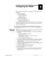
Page 49: ...guration Procedure Whether you use the front panel or a remote unit to configure the TDR60 perform the following steps to configure your system 1 Make a list of your operational requirements You must...

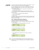
Page 50: ...ideo decoder and the audio decoders are fully auto detecting which means that the TDR60 automatically sets the video and audio parameters based on the incoming service signal Step 1 Setting the DVB De...

Page 51: ...DR60 To resolve this issue the equivalent parameter in the software settings of the remote unit must be changed to 9600 bps However the remote unit software settings must not be changed before issuing...

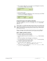
Page 52: ...factory configuration as the default In the TDR60 both the video decoder and the audio decoder are fully auto detecting which means that the TDR60 automatically sets all of the video and audio paramet...

Page 53: ...croll through the list of LNB power parameters and select the required parameter 13V 9 Press Enter to set the LNB power The demodulator is configured 10 Set the date and time 11 Select the service if...

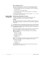
Page 54: ...band carrier is equal to the specified RF frequency minus the specified LO frequency If the entered RF or LO parameters are incorrect the actual carrier frequency will be different from the programed...

Page 55: ...the demodulator decoder and transport stream are all locked OFF if the Status LED is not illuminated at least one of the following is unlocked the demodulator decoder or transport stream Fault LED ON...

Page 56: ...e Up button If the display does not change when the Up button is pressed only one current fault exists If no current faults exist or if the current fault condition clears No Faults is displayed All cu...

Page 57: ...history log until one of the following events occur The unit s power is turned off or the unit is reset The fault history log is cleared by selecting Faults Clear from the front panel or issuing the r...

Page 58: ...DC FIFO Overflow Transport Demux Input 08 57 39 21 08 2003 QD Input Signal Loss 03 34 05 20 08 2003 DC Input Signal Loss PCR not found The query response shows The type of information queried fault lo...

Page 59: ...eo Decoder UDx User Data VBI Teletext Insertion Module Faults Descriptor Explanation Possible Cause Bad Eb N0 Input signal to noise ratio below DVB specification Insufficient transmit power improperly...

Page 60: ...he following troubleshooting tips were designed to help you diagnose and correct minor operational problems in the unlikely event that you encounter difficulties with your TDR60 If you try all of the...

Page 61: ...tance Front Panel Problems Problem The front panel is not enabled is in view only mode does not accept commands or button pushes Solutions The front panel may be in lock out mode Unlock the front pane...

Page 62: ...ted Ensure that the associated encoder is configured for the video input source that is being provided Problem Jerky or freeze frame video output Solutions Verify that the aggregate data rate does not...

Page 63: ...receive carrier frequency and the frequency determined by subtracting the LO Freq parameter from the RF Freq parameter To achieve carrier transport stream lock the difference between the two frequenc...

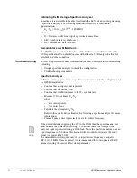
Page 64: ...ception of a signal that will guarantee flawless video performance at each Viterbi code rates is listed in the table below An Eb N0 value at least 3 dB above these limits is reasonable Eb N0 levels th...

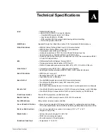
Page 65: ...al digital component video SMPTE 259M BNC connector female AUDIO PROCESSING MPEG Layer I or Layer II Sampling rates of 32 44 1 and 48 kHz Input rates from 64 to 384 kbps AUDIO OUTPUT Two AES EBU digit...

Page 66: ...56 01 0868 401B 12 02 Technical Specifications...

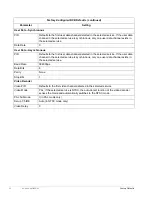
Page 67: ...audio decoder selects the first audio channel detected in the selected service VBI Format Off Demodulator RF Frequency 11210 MHz LO Frequency 10000 MHz Data Rate 8448000 bps Symbol Rate 5500187 sps Co...

Page 68: ...ice If the user data channel in the selected service is synchronous only one user data channel exists in the selected service Baud Rate 38400bps Data Bits 8 Parity None Stop Bits 1 Video Decoder Video...

Page 69: ...the filter Check the Offset parameter to confirm that the acquired carrier is within 2 Mhz of the location you specified when entering the RF and LO parameters For the procedures used to query to off...

Page 70: ...rovided in the chapter on using the front panel Aggregate Rate Bits Sec Aggregate rate is the data rate of the encoder output transport stream The transport stream can be either a single transport str...

Page 71: ...encoder input Incoming bit errors that are corrected will result in a difference between the original input and the encoded output These differences are accumulated for a fixed amount of time This ac...

Page 72: ...nalyzer Following are ways you can use a spectrum analyzer to check the configuration of the QPSK demodulator Confirm that an input signal is present Confirm that spectrum is flat Confirm that width c...

Page 73: ...n reaching max count Any substantial channel noise will cause this register to be greater than zero Reed Solomon Uncorrected This register displays the total number of byte errors that were detected b...

Page 74: ...64 01 0868 401B 12 02 QPSK Demodulator Application Notes...

Page 75: ...d PAL TV signal consists of 625 horizontal lines referred to as a frame Each frame is divided into two fields each with 312 lines The first 22 lines of each field are the VBI region the remaining line...

Page 76: ...quired video Correctly configured either manually or via auto sensing functionality for the employed VBI method All of the VBI schemes described in this document with the exception of Tiernan Propriet...

Page 77: ...nsure that the video input source is set to auto or analog Use the front panel command Config Service Video Input Source or the remote VI port FMTCTL command 3 Set the encoder to PAL mode Issue the fr...

Page 78: ...es all other VBI data Hardware Requirements Encoders require a TVIP 6025 module The TDR60 decoder processes ATSC closed captions End to End Configuration To configure the encoder and decoder for ATSC...

Page 79: ...re Requirements Encoders will properly process Tiernan closed captions with any of the following modules TVIP 6021 TVIP 6025 or TVIP 6001 The TDR60 decoder processes VBI data in its standard configura...

Page 80: ...BI CONTROL MANUAL command b Set the VBI format to Tiernan closed captions Issue the front panel command VBI Format VBI Format Tiernan CC or the remote VBI FORMAT TIERNANCC command DVB 4 2 2 Expanded W...

Page 81: ...cesses VBI data in its standard configuration End to End Configuration To configure the encoder and decoder for DVB 4 2 2 Expanded Windows operation follow these steps Encoder 1 Ensure that all other...

Page 82: ...Auto or the remote VBI CONTROL AUTO command 7 If your system requires you to manually set the type of VBI data to Expanded Windows follow these steps a Set the decoder VBI format control to manual Iss...

Page 83: ...configure the encoder to transmit closed captions ATSC CC Configures the encoder to transmit ATSC closed caption information on encodes ATSC VBI information off does not encode any ATSC VBI informatio...

Page 84: ...ext subtitle data is included Note TT Unit_ID must be set to 2 or 3 for proper decoder operations Remote Command Parameter Range Description VE ATSC_CC On Off Configures the encoder to transmit ATSC c...

Page 85: ...be included in the video output stream Note VBI Fmt Cntrl must be set to manual for this parameter to be set to off Note To ensure proper display of teletext VBI Format must be set to Off ATSCCC sets...

Page 86: ...this parameter to be set to off Note To ensure proper display of teletext VBI Format must be set to Off ATSCCC sets the VBI format to ATSC closed captions Note For proper decoding of ATSCCC VBI Contro...

Page 87: ...e unit To install the rubber feet perform these steps 1 Ensure that there are four rubber feet included in the shipping kit 2 Break the feet apart from one another Working with one rubber foot at a ti...

Page 88: ...Ensure that the installation provides the minimum required air flow clearances at the sides and rear of the unit Rear Rack Mount Instructions The rear rack mount kit contains the following items Two m...

Page 89: ...RIAL DIGIT DIGITAL AL AUDIO AUDIO J24 J24 J23 J23 J22 J22 J21 J21 ASI OUT ASI OUT SECONDAR SECONDARY PRIMAR PRIMARY MUX MUX ASI IN ASI IN LEFT LEFT ANALOG NALOG AUDIO 1A AUDIO 1A RIGHT RIGHT J4 J4 AUX...

Page 90: ...at the required air flow for safe operation is provided Rack Stability During installation consider weight distribution on the rack hazardous stability conditions may arise if units are loaded into th...

Page 91: ...ges remote unit 30 F fault LED 45 menu 20 remote commands 32 fault history log 47 viewing on front panel 47 viewing on remote device 48 faults clearing 48 command mnemonics 49 current 45 front panel L...

Page 92: ...set 35 syntax 29 teletext 36 37 76 types 28 typing 29 user data 35 36 VBI 36 37 76 video 37 remote control menu 24 remote unit command types 28 commands issuing 29 communications overview 28 error mes...

Reviews: