


Communications
IERNAN
T
Previous
More
Communications
1 2 3
4 5 6
7 8 9
- 0 .
Select
Enter
Select
Select
STATUS FAULT POWER
MPEG-2
Encoder
Previous
More
Communications
1 2 3
4 5 6
7 8 9
- 0 .
Select
Enter
Select
Select
STATUS FAULT POWER
IRD
MPEG2
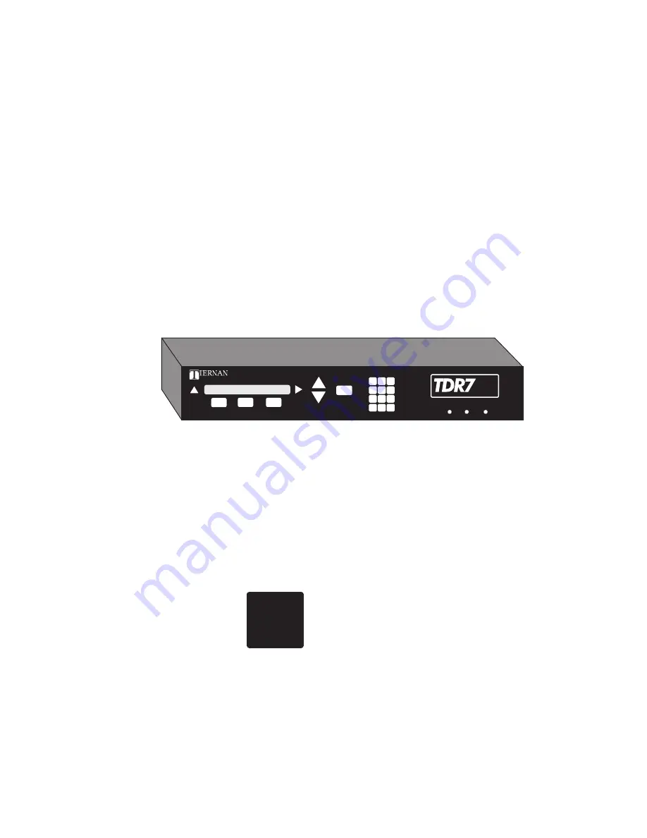
TDR7
MPEG–DVB Receiver/Decoder
Copyright 1998-1999 Tiernan Communications, Inc.
TDR7
Operator Manual, Revision K, 01/08/99
TPN: 505–002300–0001
Summary of Contents for TDR7
Page 17: ...Chapter 1 TDR7 Overview...
Page 18: ......
Page 25: ...Chapter 2 Installing the TDR7...
Page 26: ......
Page 48: ...Chapter 2 34 Installing the TDR7...
Page 49: ...Chapter 3 Using the Control Front Panel...
Page 50: ......
Page 78: ......
Page 79: ...Chapter 4 Using a Remote Control Device Interface...
Page 80: ......
Page 111: ...Chapter 5 Configuring the TDR7...
Page 112: ......
Page 151: ...Chapter 6 Troubleshooting...
Page 152: ......
Page 169: ...157 Appendixes Maintenance Glossary Warranty Specifications and Index...
Page 170: ...I...
Page 176: ...164 Maintenance...


