


Chapter 2
24
Installing the TDR7
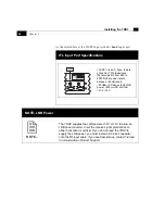
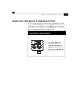
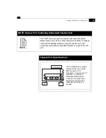
Cabling User Equipment to Audio Output Ports
The TDR7 provides two stereo audio outputs via DB–9 connectors
labeled J12 and J3, which are described below. DB–9 connector
pinouts are listed in the table below.
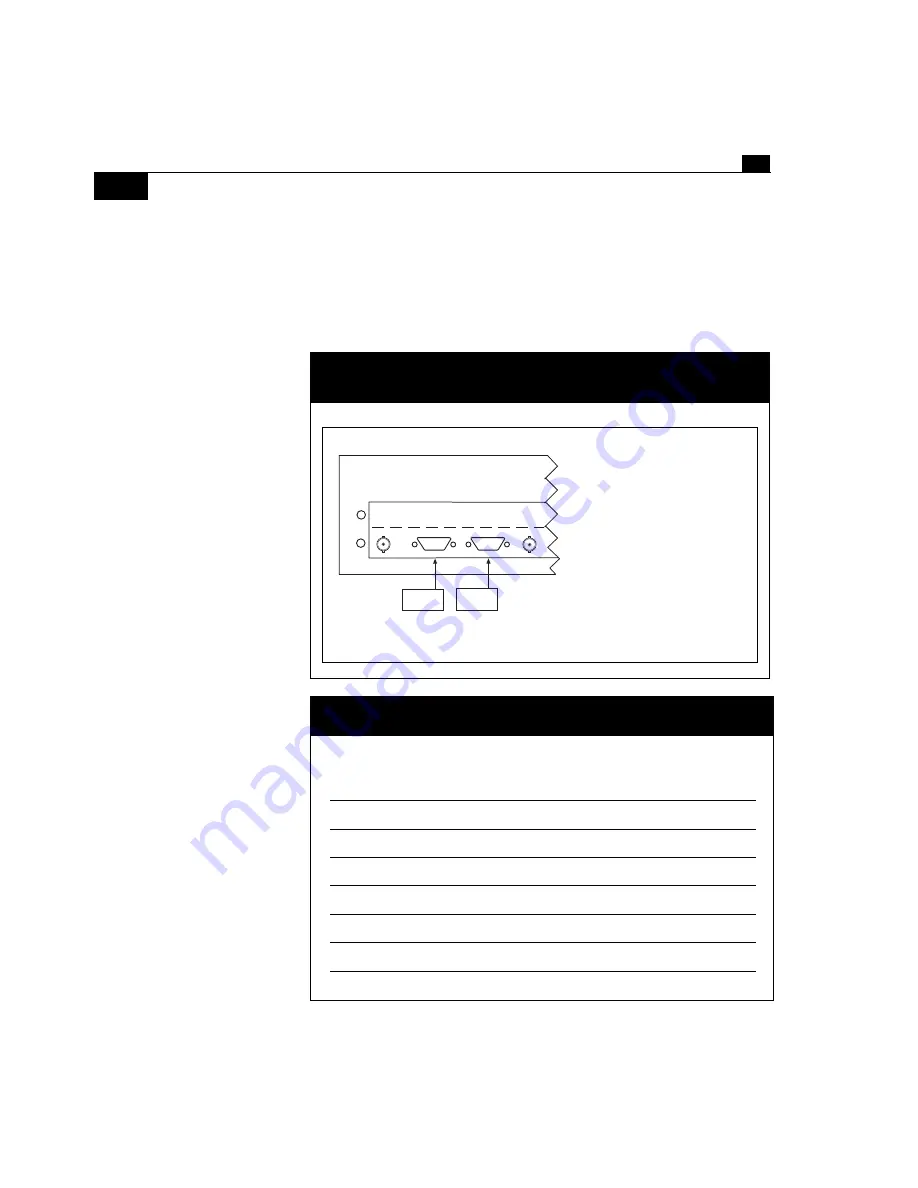
Audio Ports Specifications
Audio Output Ports Pin Assignments
Pin
Signal
Direction
1
Aud_L+
input
2
Aud_L–
input
3
input
4
Aud_R+
input
5
Aud_R–
input
6–7
GND
8
AESEBU–
input
9
GND
Composite
Audio A
Audio B
D1 Video
J12
Audio A
J3
Audio B
J12 Audio A
outputs
balanced AES/EBU or
balanced analog, +18
dBu
maximum signal level, to a
male DB –9 connector, 50
Ω
impedance.
J3 Audio B
outputs
balanced AES/EBU or
balanced analog, +18
dBu
maximum signal level, to a
male DB –9 connector, 50
Ω
impedance.
Summary of Contents for TDR7
Page 17: ...Chapter 1 TDR7 Overview...
Page 18: ......
Page 25: ...Chapter 2 Installing the TDR7...
Page 26: ......
Page 48: ...Chapter 2 34 Installing the TDR7...
Page 49: ...Chapter 3 Using the Control Front Panel...
Page 50: ......
Page 78: ......
Page 79: ...Chapter 4 Using a Remote Control Device Interface...
Page 80: ......
Page 111: ...Chapter 5 Configuring the TDR7...
Page 112: ......
Page 151: ...Chapter 6 Troubleshooting...
Page 152: ......
Page 169: ...157 Appendixes Maintenance Glossary Warranty Specifications and Index...
Page 170: ...I...
Page 176: ...164 Maintenance...


