background image


Note:

 If wir

replace, bu

1. Cont

2. Wire

3. Hex 

4. Flat 

5. Knur

6. Wire

7. Hex 

hex 

8. Inne

9. Inne

10. Pres

3-4 Conne


re guide hos

utton will res

tact tip: stan

e filling devic

nut 

square nut 

rled nut: adj

e guide nozz

nut: release

nut. 

r hex screw

r hex screw

ssure cover: 

ection  

se is damag

et by upspri

ndard is

Φ

1.0

ce goose ne


ust knurled 

zle pipe slee

e hex nut, ins


: release to 

pressure w

ed, just pres

ng automati

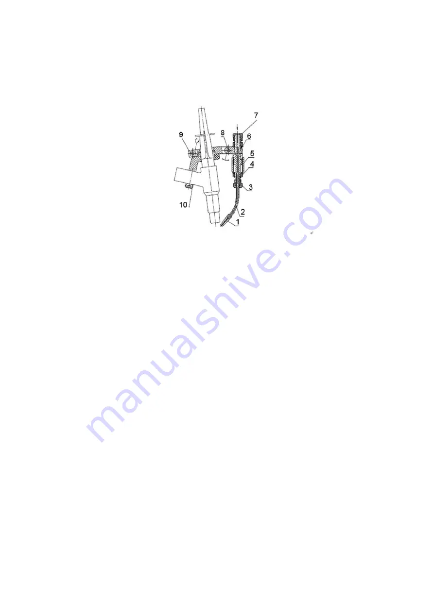
Fig. 3-3

0~

Φ

2.5. 

ck  

nut, welding

ve 

stall wire fee

adjust angle

ell after weld

ss this butto

ically.  

3-4: Wire fill

g torch barre

eding hose i

e. 

ding torch in

on, then you

ing device 

el can fine ad

into wire gui

nstallation.

can pull ou


djust up and

de nozzle p

ut wire guide


d down, rang

pipe sleeve, 

e hose. After

ge is 10mm.

then tighten

Summary of Contents for 320020-00001H

Page 1: ...TIG TIG Cold Wire Feeder ...

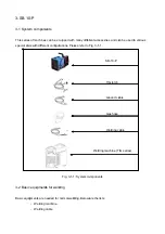
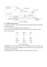
Page 2: ...nts es can be eq rent configur nts for weld needed for n machine cable uipped with rations Plea Fig 3 1 1 ding normal weld many differ ase refer to System co ding Below a rent accesso Fig 3 1 1 Welding omponents are the lists ories and ca SB 10 P TIG torch Ground ca Gas hose Welding ca machine TI an be used in able able IG series n various ...

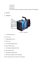
Page 3: ... now e adjustmen e now ithdraw adju e withdraw s eeding speed e feeding spe eed wire with l wire feedin manual posi 1 2 3 4 5 6 7 cable wire torch ulator gas h t knob t knob ustment kno speed d adjustmen eed hdraw switch ng auto wire tion wire wi hose gas cy Fig b nt knob h feeding swi ill feed out o ylinder to su 3 3 1 Fron itch or withdraw upply the ma nt panel achine with shielding ga as ...

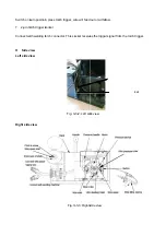
Page 4: ...ch trigger s ith welding t view view view n press torc socker torch connec ch trigger w ctor This so Fig 3 Fig 3 ire will feed ocket receive 3 2 Left sid 3 3 3 Right s out or withd es the trigge de view side view draw er signal from 4 pin 5A fuse m the torch control sock trigger ket ...

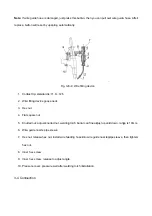
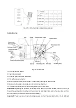
Page 5: ... is damag et by upspri ndard isΦ1 0 ce goose ne ust knurled zle pipe slee e hex nut ins release to pressure w ed just pres ng automati Fig 3 3 0 Φ2 5 ck nut welding ve stall wire fee adjust angle ell after weld ss this butto ically 3 4 Wire fill g torch barre eding hose i e ding torch in on then you ing device el can fine ad into wire gui nstallation can pull ou djust up and de nozzle p ut wire gu...

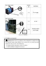
Page 6: ...k on hine mains s hine is unplu Table k is very dan g installation n the machin switch is in t ugged from 1 2 1 3 3 4 1 Conn ngerous If th n there is a ne when the OFF po the mains 2 2 4 Power supply Sock pin 1 2 1 2 3 4 nection he welding m a high risk osition box ket n 2 T 2 4 We s machine is p of very seri Descriptio Torch trigg AC36V elding mac switch sign plugged into ious injury a on ger chi...

Page 7: ...wire coatin ng resistanc wires of diff Fig 3 ers be chosen a bon steel wir minum and a Fig 3 5 andle to adju g be damag ce erent mater 3 5 1 Instal according to re stainless luminum allo 5 2 Wire fee ust wire fee ged and it rials and diam lation the size and s steel wire oys also for ed rollers l roller press will cause t meters are a d material of r copper and sure too mu he wearing as shown in f...

Page 8: ...re pres e roller or w g the pressu be smoothly void the wire a scale for w ial 5 3 Wire fee Fig nward e roller or wir ssure roller o ire feeding r ure of feedi y and there e feed rollers wire feeding ed rollers ins 3 5 4 Side re feeding ro or wire feedi roller by the ing rollers w should be a s skidding g pressure o stallation pa view oller by the s ing roller screw drive with the pre a bit brake ...

Page 9: ... device re cut off th t 15 cm part wire tube a e device dow handle back e force ding torch an trol socket o ontrol cable c of control ca ing machine e feeding bu s are corre to torch cab e will cause w rollers and i re spool will his cover is o t and make s d hold of wire ol screw rew by screw n wire spool e curve part t of wire and also into wnward k to vertical nd detach th on wire feede connect...

Page 10: ...ht kg sion mm nts list e ve oller e tube se use the w d and even m meter ameter h Sta g Table 3 Table 3 7 1 wire feeder w machine wil ainless steel 3 6 1 Techn Quantity 2 2 1 1 2 2 2 1 1 1 1 Main com with suitable l be damage SB DC Φ0 8mm Φ5 Φ30 103 20 0 15 3 l or mild stee 2 1 480 2 nical data mponents list e welding ma ed 10 P C24 m Φ2 4mm 50mm 00mm 3mm 00N 2m min 3m el solid wire 20 10 200 270 ...

Page 11: ...er is e diameter feeding ndition eding roller smoothly s worn or ubles and ca 1 Trouble Pressu pressu wears Too m wire fe If not w Contac feeding If not w If yes auses are un shooting Proble ure is smalle re is stronge easily much dust eding is not wire feeding ct face is wo g is not smo wire feeding local heats s ncertain Ho em r roller skid er roller accumulatio smooth is not smoo orn wire oth i...

Page 12: ...e feeding ng lated dry pl r do not nee ment or man r ANCE hose and wi ce normal w e of the feed g hose Wire eace Ruste ed refuel and ufacturer Kee re feeding r ire feeding der e powder an ed dirty wire d maintain u ep in ventilat oller and rep nd dirt inside e will influen sually If the ted dry plea place if worn e of wire feed ce welding s ey have prob ace n Dirt and s ding hose w seam forma blem...

Reviews: