Edition
Manual
Chapter
Page
2008-10-23 Workshop Manual, Stiga Titan 4 Hydraulic system
17
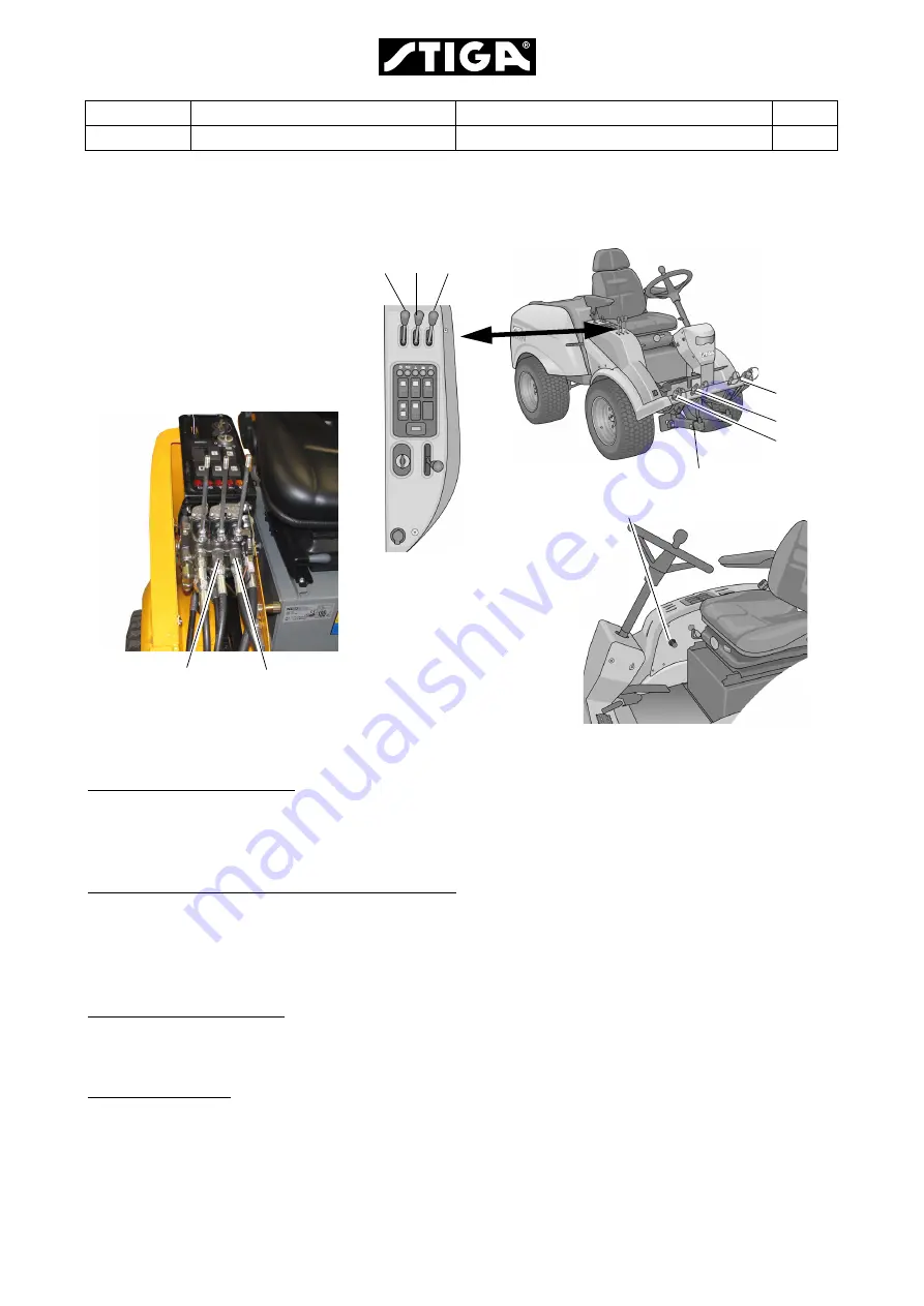
Location of actuators and hydraulic outputs at the machine
Description of components
1. Pressure limiting valve
This valve is intended to reduce the pressure when the implement lifter is forced
downwards. Otherwise the implement will be damaged and the machine would have a
tendence to rise at the front.
2 and 3. Mechanic actuated non-return valve
The valves F1 and L1 have a small oil return leakage. To prevent the implement moving
due to its own weight, the oil flow is stopped by these valves. To facilitate the flow when the
implement shall move in this direction, the valves are mechanical affected of the valve slide
to open.
4. Check valve lowering
This valve is adjustable and its purpose is to reduce the oil flow, and thus adapt the speed
to implements with different weights, when the implement lifter is lowering.
5. Collector block
The collector block collects leak oil and return oil from all hydraulic components to transit
it back to the tank.
F1 L1 R1
PTO
L
R
F
Check valve lowering (4)
3
2


