MAINTENANCE
SIDE ROTARY
Maintenance Section 4-20
© 2014 Alamo Group Inc.
MAINTENANCE
ROTARY KNIFE REPLACEMENT
1. Be sure you have a complete matching set of new knives for replacement.
2. Remove knives and inspect holes for damage. Also watch for cracks in the disk around the holes.
3. Lube threads with anti-seize, motor oil or grease. Install bolts through knife and disk from bottom side of
disk. Install new self-locking nuts and torque them to 800 ft. lbs.
4. The knives should swing freely to absorb shocks from impact when striking objects.
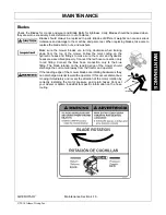
WHEN CUTTING HEAVY BRUSH, KNIFE BOLTS SHOULD BE INSPECTED HOURLY AND
RETORQUED TO 1070 DRY OR 800 OILED FT./LBS.
REPLACEMENT OF ROTARY DISK
Failure to follow the following warnings and instructions may result in serious injury or
damage to the equipment or property!
The bolts that attach the knife mo unting disk to th e spindle must be grade 8. These 5/8 inch bolts are to be
torqued according to the chart in this section.
A thread locking agent may be applied to threads of all mounting bolts before they are installed.
Disks must be inspected daily for hairline cracks between spindle mounting bolts or around the knife
mounting bolts. These cracks indicate metal fatigue caused by severe abuse. If cracks are present. the
disk must be replaced.
Inspect the disk mounting bolts daily when checking tightness of blade mounting bolts. If a disk mounting bolt is
loose, it must be removed, threads cleaned, fresh thread locking agent applied, and tightened to proper torque
value.
If a knife mounting bolt is loose, the self locking nut must be replaced as a safety precaution. Lubricate threads
with anti-seize, grease or motor oil. Place bo lts through knife and disk from bottom side of disk. Install self
locking nuts and torque them to 800 ft. lbs.
1.
WARNING:
The disk alone weighs over 100 lbs.
Be sure its weight can be supported before attempting
to replace. The use of a lift mechanism will ease replacement.
2. Remove the six disk mounting bolts and the disk from the spindle.
3. Install new disk and align with mounting bolt holes.
4. Apply a thread locking agent to all of the mounting bolts and install the bolts through the disk.
NOTE:
Disk bolts must be Grade 8.
5. Tighten bolts down and torque to values noted.
6. See knife replacement instructions for replacing the knives onto the new disk.
Summary of Contents for JD5075E T4F
Page 4: ......
Page 6: ......
Page 7: ...SAFETY SECTION...
Page 18: ...Side Rtry Safety Section 1 12 SAFETY SAFETY...
Page 27: ...Side Rtry Safety Section 1 21 SAFETY SAFETY 00756059 MOWER DECK 34852 HYDRAULIC TANK...
Page 30: ...Side Rtry Safety Section 1 24 SAFETY SAFETY...
Page 31: ...Assembly Section 2 1 ASSEMBLY SECTION JD 5075E T4F SIDE ROTARY...
Page 44: ...ASSEMBLY Assembly Section 2 14 SIDE MOWER HYDRAULIC DIAGRAM ASM C 0090 JD5075E...
Page 49: ...Operation Section 3 1 2013 Alamo Group Inc OPERATION SECTION...
Page 90: ...OPERATION SIDE ROTARY Operation Section 3 42 2014 Alamo Group Inc OPERATION...
Page 91: ...Maintenance Section 4 1 2014 Alamo Group Inc MAINTENANCE SECTION...
Page 114: ...MAINTENANCE SIDE ROTARY Maintenance Section 4 24 2014 Alamo Group Inc MAINTENANCE...
Page 115: ...PARTS SECTION JD5075E T4F SIDE ROTARY...
Page 117: ...PARTS ORDERING GUIDE 2019 Alamo Group Inc Parts Section 3 JD5075E SIDE ROTARY...
Page 118: ...TRACTOR MOUNT KIT 2019 Alamo Group Inc Parts Section 4 JD5075E SIDE ROTARY...
Page 120: ...TRACTOR MOUNT KIT HYDRAULICS 2019 Alamo Group Inc Parts Section 6 JD5075E SIDE ROTARY...
Page 124: ...DRAFT BEAM TSR MOWER 2019 Alamo Group Inc Parts Section 10 JD5075E SIDE ROTARY...
Page 126: ...DRAFT BEAM TM MOWER 2019 Alamo Group Inc Parts Section 12 JD5075E SIDE ROTARY...
Page 129: ...NOTES 2019 Alamo Group Inc Parts Section 15 JD5075E SIDE ROTARY...
Page 133: ...PARTS SECTION COMMON SIDE ROTARY...
Page 134: ...NOTES...
Page 137: ...PARTS ORDERING GUIDE 2014 Alamo Group Inc Parts Section 6 5 COMMON SIDE ROTARY...
Page 138: ...CABLE DRAFT BEAM ASSEMBLY 2014 Alamo Group Inc Parts Section 6 6 COMMON SIDE ROTARY...
Page 140: ...COMBO DRAFT BEAM ASSEMBLY 2014 Alamo Group Inc Parts Section 6 8 COMMON SIDE ROTARY...
Page 142: ...60IN SIDE CABLE TM ROTARY MOWER 2014 Alamo Group Inc Parts Section 6 10 COMMON SIDE ROTARY...
Page 144: ...72IN SIDE CABLE TM ROTARY MOWER 2014 Alamo Group Inc Parts Section 6 12 COMMON SIDE ROTARY...
Page 146: ...60IN SIDE COMBO TM ROTARY MOWER 2014 Alamo Group Inc Parts Section 6 14 COMMON SIDE ROTARY...
Page 148: ...72IN SIDE COMBO TM ROTARY MOWER 2014 Alamo Group Inc Parts Section 6 16 COMMON SIDE ROTARY...
Page 150: ...60IN SIDE TM CHAIN GUARDS 2014 Alamo Group Inc Parts Section 6 18 COMMON SIDE ROTARY...
Page 152: ...72IN SIDE TM CHAIN GUARDS 2014 Alamo Group Inc Parts Section 6 20 COMMON SIDE ROTARY...
Page 154: ...60IN SIDE TSR ROTARY MOWER 2014 Alamo Group Inc Parts Section 6 22 COMMON SIDE ROTARY...
Page 156: ...60IN SIDE TSR REAR GUARDS 2014 Alamo Group Inc Parts Section 6 24 COMMON SIDE ROTARY...
Page 158: ...SIDE ROTARY CASTER WHEEL ASSEMBLY 2014 Alamo Group Inc Parts Section 6 26 COMMON SIDE ROTARY...
Page 162: ...TM MOWER SPINDLE ASSEMBLY 2014 Alamo Group Inc Parts Section 6 30 COMMON SIDE ROTARY...
Page 164: ...TSR MOWER SPINDLE ASSEMBLY 2014 Alamo Group Inc Parts Section 6 32 COMMON SIDE ROTARY...
Page 166: ...ROTARY MOTOR BREAKDOWN 2014 Alamo Group Inc Parts Section 6 34 COMMON SIDE ROTARY...
Page 168: ...60IN TSR ROTARY MOTOR BREAKDOWN 2014 Alamo Group Inc Parts Section 6 36 COMMON SIDE ROTARY...
Page 170: ...FRONT HYDRAULIC PUMP BREAKDOWN 2014 Alamo Group Inc Parts Section 6 38 COMMON SIDE ROTARY...
Page 191: ...BRAKE VALVE HYDRAULIC SCHEMATIC 2014 Alamo Group Inc Parts Section 6 59 COMMON SIDE ROTARY...
Page 195: ...SWITCH BOX SCHEMATIC 2014 Alamo Group Inc Parts Section 6 63 COMMON SIDE ROTARY...
Page 196: ...NOTES 1 2014 Alamo Group Inc Parts Section 6 64 COMMON SIDE ROTARY...
Page 197: ...WARRANTY SECTION Warranty Section 7 1...
Page 198: ......
Page 202: ...Printed in USA Tiger Corporation...

