OPERATION
Boom
Operation Section 3-41
©2011 Alamo Group Inc.
OPERA
TION
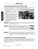
11.1 Placing Boom Arm on Boom Arm Rest - For Standard Equipment
Before transporting tractor between locations, idle
the tractor engine, disengage the attached head,
and wait for all head motion to come to a complete
stop. Place the boom in its storage cradle rest
support and then turn the joystick master switch to
the OFF position.
•
Retract Deck Roll cylinder completely.
•
Push Secondary cylinder approximately 1/2
way out.
•
Raise Main boom approximately to 60°.
•
Swing boom back slowly until it is straight
back.
•
For a 3-point boomrest or a single column
boomrest, position the secondary in the
cradle. Carefully avoid pinching any hoses.
•
For a open stow style boomrest, lower the
Main boom onto rest and bring the Secondary
boom in until it is sitting on the boomrest.
•
For a Legal Stow style boomrest, retract the
secondary and knuckle cylinders completely.
Lower the Main boom onto rest. Slowly
extend the secondary cylinder until the
secondary boom contracts the side of the boomrest saddle. Next, slowly extend the knuckle cylinder until
the secondary sets on the bottom part of the boomrest saddle.
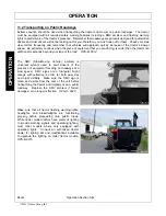
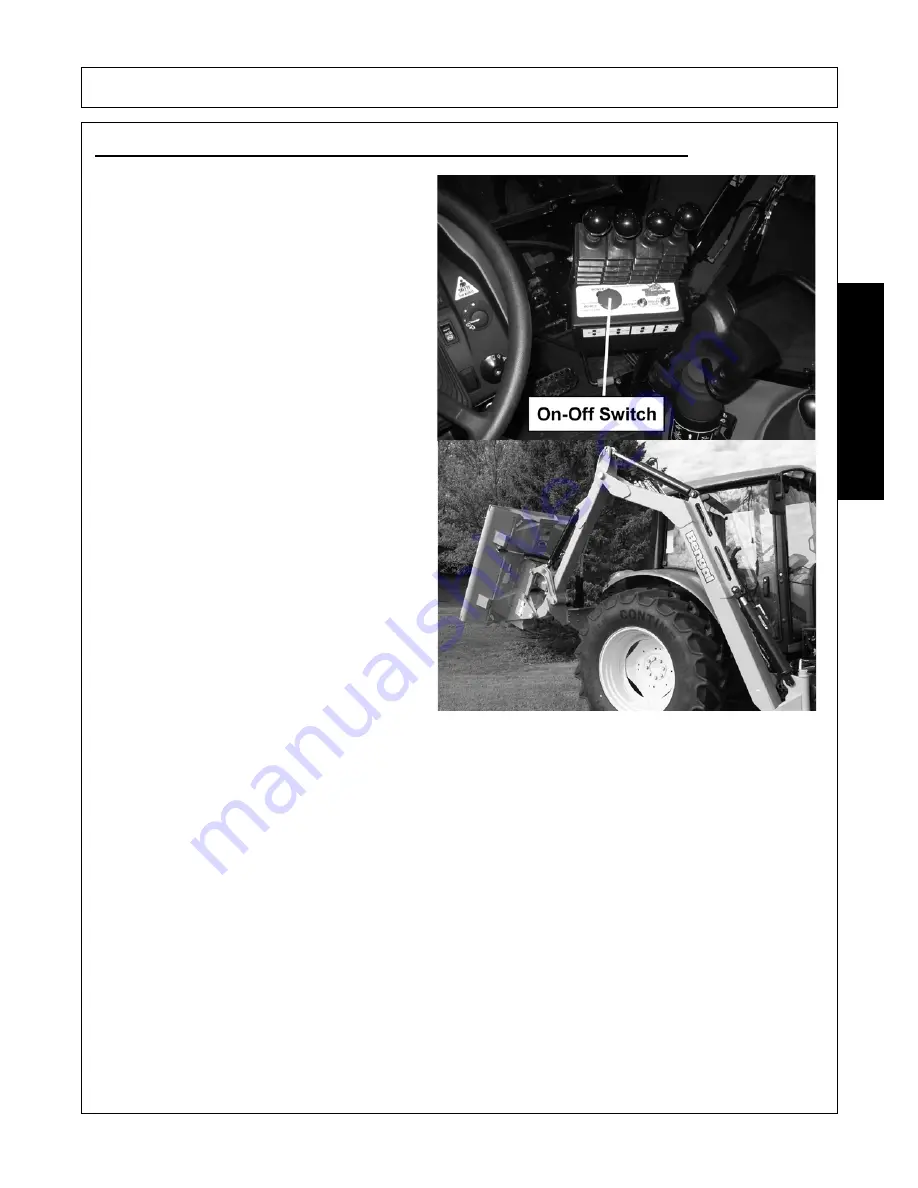
The boom is now in the transport position. Turn on any electronic travel locks at the switchbox.
To remove the boom from the Boom Rest, first turn off any electronic travel locks at the switchbox then retract
the knuckle cylinder (if applicable) then swing the Secondary boom out. Raise the Main boom approximately 6
inches. Swivel the boom forward to the desired position.
OPS-B- 0013_D
Summary of Contents for JOHN DEERE 5083E
Page 4: ......
Page 6: ......
Page 7: ...Bengal Boom Safety Section 1 1 SAFETY SAFETY SECTION ...
Page 29: ...Bengal Boom Safety Section 1 23 SAFETY 34852 HYDRAULIC TANK TB1011 MOWER DECK ...
Page 32: ...Bengal Boom Safety Section 1 26 SAFETY ...
Page 33: ...Assembly Section 2 1 ASSEMBLY SECTION JD5101E LYNX ...
Page 53: ...Operation Section 3 1 2011 Alamo Group Inc OPERATION SECTION ...
Page 98: ...OPERATION Boom Operation Section 3 46 2011 Alamo Group Inc OPERATION ...
Page 99: ...Maintenance Section 4 1 2011 Alamo Group Inc MAINTENANCE SECTION ...
Page 106: ...MAINTENANCE Boom Maintenance Section 4 8 2011 Alamo Group Inc MAINTENANCE ...
Page 127: ...MAINTENANCE Boom Maintenance Section 4 29 2011 Alamo Group Inc MAINTENANCE ...
Page 129: ...PARTS SECTION JD 5101E LYNX BOOM ...
Page 130: ...NOTES ...
Page 132: ...NOTES 2011 Alamo Group Inc Parts Section 5 4 JD5101E LYNX ...
Page 133: ...PARTS ORDERING GUIDE 2011 Alamo Group Inc Parts Section 5 5 JD5101E LYNX ...
Page 136: ...TRACTOR MOUNT KIT HYDRAULICS 2011 Alamo Group Inc Parts Section 5 8 JD5101E LYNX ...
Page 144: ...TRACTOR MOUNT KIT LOADER HYDRAULICS 2011 Alamo Group Inc Parts Section 5 16 JD5101E LYNX ...
Page 146: ...BOOM MOUNT KIT 2011 Alamo Group Inc Parts Section 5 18 JD5101E LYNX ...
Page 149: ...NOTES 1 2011 Alamo Group Inc Parts Section 5 21 JD5101E LYNX ...
Page 150: ...BOOMREST SINGLE COLUMN 2011 Alamo Group Inc Parts Section 5 22 JD5101E LYNX ...
Page 163: ...PARTS SECTION COMMON LYNX BOOM ...
Page 164: ...NOTES ...
Page 167: ...PARTS ORDERING GUIDE 2011 Alamo Group Inc Parts Section 6 5 COMMON LYNX ...
Page 168: ...NOTES 2011 Alamo Group Inc Parts Section 6 6 COMMON LYNX ...
Page 170: ...BOOM ASSEMBLY 2011 Alamo Group Inc Parts Section 6 8 COMMON LYNX ...
Page 178: ...ROTARY MOWER SPINDLE ASSEMBLY 2011 Alamo Group Inc Parts Section 6 16 COMMON LYNX ...
Page 180: ...BOOM ROTARY PIVOT ASSEMBLY 2011 Alamo Group Inc Parts Section 6 18 COMMON LYNX ...
Page 182: ...50IN FLAIL DRIVE ASSEMBLY 2011 Alamo Group Inc Parts Section 6 20 COMMON LYNX ...
Page 188: ...63IN FLAIL DRIVE ASSEMBLY 2011 Alamo Group Inc Parts Section 6 26 COMMON LYNX ...
Page 190: ...63IN FLAIL MOWER ASSEMBLY 2011 Alamo Group Inc Parts Section 6 28 COMMON LYNX ...
Page 192: ...BOOM FLAIL PIVOT ASSEMBLY 2011 Alamo Group Inc Parts Section 6 30 COMMON LYNX ...
Page 200: ...FRONT HYDRAULIC PUMP 2011 Alamo Group Inc Parts Section 6 38 COMMON LYNX ...
Page 202: ...50IN AND 60IN ROTARY MOTOR BREAKDOWN 2011 Alamo Group Inc Parts Section 6 40 COMMON LYNX ...
Page 204: ...50IN AND 63IN FLAIL MOTOR BREAKDOWN 2011 Alamo Group Inc Parts Section 6 42 COMMON LYNX ...
Page 206: ...COOLER OPTION 2011 Alamo Group Inc Parts Section 6 44 COMMON LYNX ...
Page 210: ...MANUAL LIFT VALVE SCHEMATIC 2011 Alamo Group Inc Parts Section 6 48 COMMON LYNX ...
Page 213: ...BRAKE VALVE HYDRAULIC SCHEMATIC 2011 Alamo Group Inc Parts Section 6 51 COMMON LYNX ...
Page 214: ...NOTES 1 2011 Alamo Group Inc Parts Section 6 52 COMMON LYNX ...
Page 215: ...CLEAN CUTTER HEAD 2011 Alamo Group Inc Parts Section 6 53 COMMON LYNX ...
Page 216: ...CLEAN CUTTER ASSEMBLY 2011 Alamo Group Inc Parts Section 6 54 COMMON LYNX ...
Page 217: ...CLEAN CUTTER OPERATION 2011 Alamo Group Inc Parts Section 6 55 COMMON LYNX ...
Page 218: ...CLEAN CUTTER OPERATION CONTINUED 2011 Alamo Group Inc Parts Section 6 56 COMMON LYNX ...
Page 219: ...CLEAN CUTTER MAINTENANCE 2011 Alamo Group Inc Parts Section 6 57 COMMON LYNX ...
Page 221: ...CARBIDE TIP REPLACEMENT 2011 Alamo Group Inc Parts Section 6 59 COMMON LYNX ...
Page 222: ...NOTES 2 2011 Alamo Group Inc Parts Section 6 60 COMMON LYNX ...
Page 223: ...FIRE SUPRESSION SYSTEM 2011 Alamo Group Inc Parts Section 6 61 COMMON LYNX ...
Page 224: ...FIRE SUPRESSION SYSTEM PARTS 2011 Alamo Group Inc Parts Section 6 62 COMMON LYNX ...
Page 227: ...WETCUT 2011 Alamo Group Inc Parts Section 6 65 COMMON LYNX ...
Page 230: ...WETCUT TANK PLUMBING 2011 Alamo Group Inc Parts Section 6 68 COMMON LYNX ...
Page 232: ...WETCUT SPRAYER HEAD ASSEMBLY 2011 Alamo Group Inc Parts Section 6 70 COMMON LYNX ...
Page 234: ...WETCUT CABLES 2011 Alamo Group Inc Parts Section 6 72 COMMON LYNX ...
Page 235: ...WARRANTY SECTION Warranty Section 7 1 ...
Page 236: ... ...
Page 240: ...Printed in USA Tiger Corporation ...


