Bridge-Box User's Manual
English
6 / 48
tiko Energy Solutions AG
IM-0007-0002 Rev. 5
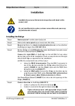
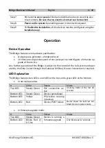
Step 7
Put back the
cover panel
of the home distribution box to cover the elec-
trical contacts.
Be sure that no electrical contact can be touched
.
Step 8
Power on the system
by enabling power in the electrical panel.
Step 9
To
finalize the installation
, all tiko devices must be configured using the
installation app
.
Operation
Device Operation
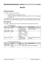
The Bridge features one hardware push button:
•
A single press generates a hardware reset
•
10 times pressing at the speed of one press per second triggers a firmware up-
grade of the device.
Any further operation of the Bridge is subject to the control of the full system and oper-
ated by the Data Center through the Gateway (M-Box). No user interaction is required.
LED Explanation
The Bridge features two LEDs: a red LED at the top, and a green LED at the bottom.
•
In normal operation:
#
Color
Status
Notes
Top LED
Steady Green
PLC connection ac-
tive
incoming traffic in the last 60
seconds
Bottom LED
Steady Green
Device operational
Bottom LED
Yellow
PSU failure: running
in backup
Bottom LED
Red
Device POST failure
Device Power-On Self-Test has
failed. Device requires service.
•
In firmware upgrade mode:
#
Color
Status
Notes
Top LED
Steady Green
Device is running a
firmware upgrade
Bottom LED
Blinks Red @
0.5 Hz
One blink each 2 seconds.
Summary of Contents for Athos
Page 46: ...Notes Notizen Notes Note Opmerkingen 46 48 tiko Energy Solutions AG IM 0007 0002 Rev 5 ...
Page 47: ...Notes Notizen Notes Note Opmerkingen 47 48 tiko Energy Solutions AG IM 0007 0002 Rev 5 ...
Page 48: ...Bridge Box User s Manual 48 48 tiko Energy Solutions AG IM 0007 0002 Rev 5 Line in Neutral in ...


