TDFM-136B Operating Instructions
08RE399
S E C T I O N 1
INTRODUCTION
This section provides an overview of the basic transceiver operation, it is broken into three
subsections as follows:
•
an overview of the controls and display information
•
a description of basic use of the transceiver
•
an introduction to the transceiver command functions
1.1
Controls and Display
This section provides basic information on the controls and display information provided for the user
on the front panel of the transceiver.
1.1.1
Front Panel Layout and Controls
All the user interface controls and display information are available to the user on the front panel of
the transceiver, with the exception of the PTT control, which is activated by an external button. The
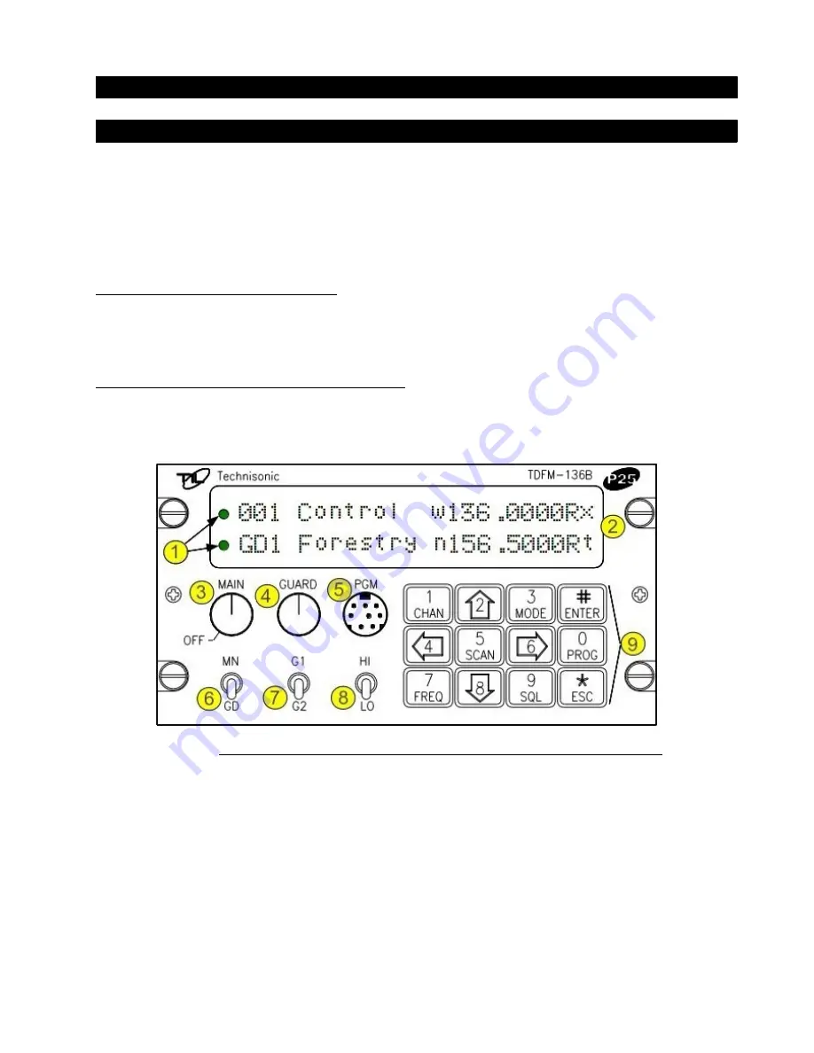
front panel layout of the TDFM-136B is shown in figure 1-1 below.
Figure 1-1. The TDFM-136B front panel showing control & display features.
The control and display features are identified as follows:
1.
LED channel squelch indicators – light on signal received (top=Main, bottom=Guard).
2.
Channel parameter display – two line by 24 character LED display (top=Main, bottom=Guard).
3.
Power ON/OFF switch and Main channel volume control (rotary encoder, with p/b switch).
4.
Guard channel volume control (rotary encoder with p/b switch) and Squelch defeat.
5.
Data port – for use with KVL 3000+ keyloader or TDP-136 Programming software.
6.
Main/Guard switch (toggle) – selects active channel (main or guard), for transmit and edit.
7.
Guard 1 or 2 switch (toggle) – selects guard memory (GD1 or GD2), for transmit and edit.
8.
Transmit Power switch (toggle) – selects transmit power, high (10W) or low (1W).
9.
Keypad (12 push buttons) – control other transceiver features (described below).
Technisonic Industries Ltd.
1


