52
53
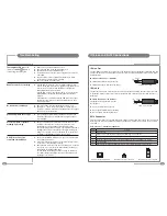
Troubleshooting
The red/green LED is not lit
(Press the POWER (
) button to
check if the green LED lights)
Remote control is not working
No sound from the Mirage
Sound and picture out of sync
Poor DTV picture or picture
breaking up ‘blocking’
A Sky™ box can not be
controlled via the Mirage
☛
Make sure any isolation switch is set to on.
☛
Check that the LED on the AC/DC adaptor is lit.
☛
Push the mains lead in to AC/DC adaptor.
☛
Try the mains lead on another piece of equipment to prove the
lead is OK.
☛
Connect another piece of equipment to the Mirage’s mains
socket to make sure the socket is working.
☛
Check the consumer unit (fuse box).
☛
If the IR LED on a remote control is viewed through a digital
camera, the IR LED will be seen to light when any button on the
remote control is pressed. If the IR LED does not light the
battery/batteries should be replaced.
If the IR LED is seen to light but the remote control only works
within 500 mm of the Mirage, the battery/batteries should be
replaced.
If the batteries are replaced and the IR LED still does not light
the remote control is faulty or the battery/batteries have been
incorrectly installed.
☛
Check the volume level and that the Mute function is off.
☛
Analogue TV – check the correct system is selected for your
country. For example, in the UK the setting must be I. See pages
26 and 27 for more information.
☛
This is usually a digital broadcast fault which clears when an
alternative channel is selected and then the original channel
selected again.
☛
Refer to a professional aerial installer. This can be due to the
condition of the aerial, the location of the aerial, the cable
quality/length, or other equipment attenuating the signal.
Note: Even though other TVs display a good picture in the same
building it does not prove the quality of the signal reaching the
Mirage. The only way is to try an alternative TV on the aerial to
the Mirage or the Mirage in a known, good location.
☛
Refer to the installation instructions on page 15, check the LED
on the Remote-Link is lit.
☛
If the LED on the Remote-Link is lit, check that the Sky remote
control does control the Sky box directly.
☛
Check that the connections and set up of the Sky box, as shown
on page 15, are correct. Note the output channel of the Sky™
box whilst on the RF OUTLETS page.
Perform ATV Manual Tuning as shown on page 27 and tune to
the output channel of the Sky™ box’s RF2 outlet. Ensure that
the Mirage is set to PAL I.
IR Links and RJ12 Connections
IR Link Out
The IR Link Out is a 3.5 mm mono jack socket. The IR signal sensed by the Mirage is outputted from this
socket to an IR emitter. This will enable the remote control of external equipment, such as a DVD player,
from the Mirage.
IR Link Out Connections – IR Emitter
IR emitter LED positive terminal to the Tip.
IR emitter LED negative terminal to the Sleeve.
IR Link In
The IR Link In is a 3.5 mm stereo jack socket. This socket allows an auxiliary IR sensor to be connected
to the Mirage, which enables remote control of the Mirage from a different point other than the front of
the Mirage.
IR Link In Connections – IR Receiver
The Mirage will 5v DC to power
the IR sensor.
IR 5v DC terminal to the Tip.
IR sensor signal output terminal to the Ring.
IR sensor negative terminal to the Sleeve.
3.5 mm mono jack plug
Tip
Sleeve
Ring
3.5 mm stereo jack plug
Tip
Sleeve
RJ12 Connector
This connector is for Hotel TV System Integration. The RJ12 allows command codes to pass to and from
the Mirage. The RJ12 pin assignment is internally configurable, to allow the connection of various Hotel
TV Systems.
RJ12 Connector – Standard Configuration
Pin No
Function
1
Not Connected
2
Command code from the external equipment to the Mirage. (0 V/5 V nominal)
3
Not Connected
4
Mirage On signal from the Mirage to the external equipment. (On = 5 V, Standby = 0 V nominal)
5
0 V – DC ground
6
Demodulated IR signal from the Mirage IR sensor to the external equipment. (0 V/5 V nominal)
Connector on the Interface PCB
1 6
Male RJ12 connector – front view
1 6
Male RJ12 connector – top view
1 6


