background image

10

11

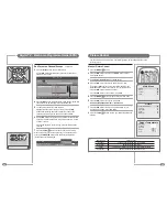
Installing the Front Plate

Installing the Front Plate

Note: A glass carrier/suction lifter is required.

Checking back box prior to installation of front plate

Before commencing the installation of the front plate the 
polystyrene blanking panel must be removed from the back box. 
The next step is to ensure that the appropriate cables and their 
connectors are  present within the back box.

It is important to ensure that the flange inside the back box is 
cleaned using a grease removal agent and allowed to dry. The 
space between the back box and front plate must be even on all 
four sides. If the flange needs to be straightened, this must be 
done before proceeding any further. This is very  important, as 
any damage will affect the unit’s waterproofing capabilities.

Installation of the front plate

Remove the front plate from its packaging and place the remote control 

to one side.

Introduce the lower front edge of the unit into the box and fit the earth 
straps to the two Earthing screws as indicated by the green labels on 

the rear of the front plate. Connect all cables to their respective sockets 

(refer to pages 5 to 9 of these instructions).

The next step is to remove the soft adhesive protector 

from the top length of special Velcro‚ and press the 
front plate into the back plate (it may be necessary to 

adjust the position of the cables to achieve a good fit).

The unit installation must comply with all relevant electrical safety regulations before turning the mains 
supply to the 12VDC power adaptor on using the remote pull switch. The unit should now show a red 
indicator light showing that it is in standby mode. 

The next step is to tune the unit as detailed on pages 17 to 20 
and 22.

Once you are satisfied that the unit is tuned and working correctly, 
press the Power 0/I button on the remote control to put the unit in 
standby mode and isolate the unit using the remote pull switch. 

Gently remove the front plate using a suction lifter. Do not use a 
lever to remove the front plate as this will invalidate your 
guarantee. Next, remove the self-adhesive protectors from the side 
and bottom Velcro strips and press the front panel into the back 
box with reasonable force. Take care to apply force to all four sides 
of the box. Restore mains power using the remote pull switch and 
press the Power 0/I button on the remote control to turn the unit on 
again and check that it is still working correctly.

Sealing the unit

When you are sure that the unit is installed correctly put it in standby mode and apply a clear silicone 
sealant to the joint between the sides of the back box and the sides of the front plate. Ensure that the 

silicone is worked into the space evenly and is applied 
without any gaps, bubbles or voids. Wipe any excess 

silicone sealant away and check for any imperfections. 
Rectify any errors as necessary. 

This seal is essential for 

the reliable and safe operation of the TileVision

®

 and 

must be completely waterproof.

Sealing Tip

: To achieve a neat seal easily it may be found useful 

to use masking tape around 

the TileVision

®

 glass screen 

and the surrounding tiles, just 

leaving sufficient gap to apply 

the silicone sealant around the 

joint between the sides of the back 

box and front plate. The acrylic surround can be fitted using silicone 
sealant once the tape is removed. 

Fitting the acrylic surround

The mirrored acrylic surround is a cosmetic addition and has no bearing on 

the integrity of the waterproof seal of the TileVision

®

.

If the surround is being fitted to the TileVision

®

, the same silicone 

sealant used to seal the screen into the back box can be used to fasten 

the surround to the wall.

Lay the surround on a flat surface and apply the silicone to the matt 

grey surface as shown. 

Once the adhesive has 

been applied, align the 

surround with the 

TileVision

®

 using a spirit 

level as a guide and 

press the acrylic 

surround firmly to 
the wall.

After the silicone 

sealant has hardened the 

protective film can be remove from the front of the surround.

Cleaning Instructions 

To clean the screen and surround, use only a soft damp cloth. Under no circumstances are 

abrasive cleaners to be used, failure to observe this warning will invalidate your guarantee.

all of the

flange must

be cleaned

only the top

strip is removed

before tuning

fill all the space between

the edge of the screen

and the back box

Tile

Back box

Grout

Velcro

Masking tape

Silicone

Screen

apply the adhesive

on the grey side of

the mirrored surround

Note

: It is the installer’s responsibility to ensure that the TileVision

®

 unit is installed 

and sealed correctly, failure to do so will invalidate your guarantee. The unit will 
require cleaning and re-sealing after any servicing/repair operation.

Summary of Contents for TV/17/FR5/PS

Page 1: ...17 23 DVB T the bathroom television HIGH DEFINITION MULTIMEDIA INTERFACE TM ...

Page 2: ...CORDANCE WITH THE INSTALLATION INSTRUCTIONS CAUTION DO NOT REMOVE COVER NO USER SERVICEABLE PARTS INSIDE REFER SERVICING TO QUALIFIED SERVICE PERSONNEL BEWARE OF STATIC SENSITIVE PARTS 17 23 DVB T This symbol is intended to alert the user to the presence of important operating and maintenance servicing instructions in the literature accompanying the appliance RoHS COMPLIANT This product contain El...

Page 3: ...tion TV Mode 15 On screen Menus and Displays TV Mode 16 Tuning Setup and Editing Analogue TV Programmes Auto Programme 17 Tuning Setup and Editing Analogue TV Programmes Manual Programme 18 Tuning Setup and Editing Analogue TV Programmes Edit Delete Select Programmes 19 Tuning Setup and Editing Analogue TV Programmes Moving and Skipping Programmes 20 Auto Tuning Digital TV 21 Digital TV Programme ...

Page 4: ... Full function remote control illustrated without sliding cover TV 17 Main Connector Array DC12V Power In HDMI High Definition Multimedia Interface In S VIDEO In S VIDEO Audio In Left White Right Red EURO SCART RGB FB AV In AV Out SVC Port connect for service only Internal Antenna Antenna Input 75Ω 1 2 3 4 6 5 7 8 1 2 3 4 5 6 7 8 12VDC S Video HDMI Audio L R EURO SCART Internal Antenna SVC Port An...

Page 5: ...s from the back box to these points Power Socket The Power socket 1 is located at the extreme left of the connection array Speaker Connections The speakers should be connected after the Earth straps to the rear of the front plate as detailed on page 10 of these operating instructions The speaker connection block is found on the right of the rear of the front plate Lift one of the lugs push one con...

Page 6: ...onnected to a separate amplifier to allow integration with a multi room audio video system This should be carried out by a qualified engineer Adaptors are commercially available to allow video and audio equipment to be connected to the TileVision via the EURO SCART socket See the examples in diagrams B SCART to RCA C SCART to RCA and D SCART to COMPONENT When connecting COMPONENT video via the SCA...

Page 7: ... mains power using the remote pull switch and press the Power 0 I button on the remote control to turn the unit on again and check that it is still working correctly Sealing the unit When you are sure that the unit is installed correctly put it in standby mode and apply a clear silicone sealant to the joint between the sides of the back box and the sides of the front plate Ensure that the silicone...

Page 8: ...dual language broadcasts 9 Menu button Displays the Main Menu 10 TV AV button Selects between DTV TV SCART COMPONENT S VIDEO or HDMI mode Clears the menu from the screen 11 Menu left right buttons Menu and EPG navigation 12 Menu up down buttons Menu and EPG navigation 13 OK button Accepts your selection or displays current mode 14 VOL Volume up down buttons Adjust the volume 15 Sleep button Sets t...

Page 9: ...d Special Setup Input Selection DTV TV SCART COMPONENT S VIDEO HDMI P 1 Sound Mode Mono Dynamic Flat Auto A Language English Norsk Deutsch Svenska Français Romaneste Español Polski Italiano Nederlands Dansk Hrvatski Switching the TileVision On Off Selecting your On screen Language 1 To switch your TileVision on press the POWER button 2 To switch your TileVision to standby press the POWER button ag...

Page 10: ...mmes will be stored Tuning Setup and Editing Analogue TV Programmes On screen Menus and Displays TV Mode Manual Programme Programme 1 System I Channel V UHF 55 Name BBC 1 Finetune 0 Memorize Setup Auto programme Manual programme Programme edit Clock Language Picture Colour Temperature Contrast 75 Brightness 65 Colour 75 Sharpness 80 Sound Equalizer Balance 0 AVL Off SRS WOW On Special N R Mode2 Bl...

Page 11: ...frica DK Russia China Eastern Europe L France 7 Press UD buttons to select Channel Then press the R button to select V UHF or Cable 8 Press the UD buttons to select V UHF or Cable as required and press the R button to confirm Select the channel number either directly with the number buttons or the UD buttons Press the R button to confirm 9 You can assign a programme name with up to eight character...

Page 12: ...Receivable Digital Channels 1 Press the MENU MENU button to display Main Menu in the DTV mode 2 On the Main Menu use the UD buttons to select DTV System 3 Press R button to enter DTV System menu 4 On the DTV System menu press the UD buttons to select DTV Scanning 5 Press the R button to start DTV scanning The DTV Scanning menu is displayed and the DTV Scanning starts immediately Scanning tuning an...

Page 13: ... can view the programme information at any time by pressing the OK OK button while watching a programme The banner will be cleared from the screen after the preset time Detailed Programme Information You can see more detailed information about the current programme at any time by pressing the INFO button Press the INFO button again to remove the banner from the screen The layout of information con...

Page 14: ...uage that subtitles will be displayed in at the bottom of the screen when Subtitles are switched on Press the TV AV TV AV button to return to normal TV viewing Subtitles can only be switched on or off with the full function remote control Press the Subtitle button to display the Subtitle Option press the OK button to confirm the option shown or press the Subtitle button to hide the Subtitle Option...

Page 15: ...ss the UD buttons to select Signal Strength and use the R button to view the Signal Strength banner 6 You can view the signal strength reception for the channel that is currently being viewed 7 Press the TV AV TV AV button to return to normal TV viewing Digital TV Basic Operation D T V S e t u p B a c k MENU S t o r e OK E x i t TV AV Banner Display Time 3 seconds Subtitle Language English Audio L...

Page 16: ...ct On or Off 5 Press the TV AV TV AV button to return to normal TV viewing Digital TV Basic Operation Selecting a Menu Language The menu can be displayed on the screen in a desired language 1 Press the MENU MENU button to display the Main Menu 2 On the Main Menu Use the UD buttons to select DTV System 3 Press the R button to enter the DTV System menu 4 On the DTV System menu press the UD buttons t...

Page 17: ...he programme listing Digital TV Electronic Programme Guide EPG Digital TV Electronic Programme Guide EPG D T V E P G Tue 2 Wed 3 Thu 4 Fri 5 Sat 6 Sun 7 Today Aug 01 2007 00 51 Mon 1 Service Category All Services Services 2 BBC TWO 3 ITV1 4 Channel 4 5 Five 6 ITV2 7 BBC THREE 9 BBC FOUR 10 ITV3 01 05 Programme A 02 35 Programme B 03 55 Programme C 06 00 Programme D 06 20 Programme E 06 35 Programm...

Page 18: ...nnel in it s new position in the list Press the R button to cancel moving a channel that has been selected 7 Press the TV AV TV AV button to return to normal TV viewing When user profiles have been defined they can be accessed by pressing the PROFILE button when the General Programme Information banner is displayed Digital TV Electronic Programme Guide EPG D T V E P G Tue 2 Wed 3 Thu 4 Fri 5 Sat 6...

Page 19: ...D buttons and use the LR buttons to select ON or OFF 10 Press the MENU MENU button to return to the preceding menu or the TV AV TV AV button to return to normal TV viewing Picture Control Auto Picture Control The Picture options Dynamic Standard Mild and Game are programmed for optimum picture reproduction at the factory and cannot be changed Picture Effect 1 Press the PICTURE button on the full f...

Page 20: ...tedly press the I II I II button to select the sound output L R Audio signal from audio L input is sent to the left speaker and audio signal from audio R input is sent to the right speaker L L Audio signal from audio L input is sent to the left and right speakers R R Audio signal from audio R input is sent to the left and right speakers Mono Sound Selection If the signal is weak in TV mode switch ...

Page 21: ...f you select Auto Sleep the TileVision will automatically switch to standby approximately ten minutes after current channel stops broadcasting 1 Press the MENU MENU button and press the UD buttons to select the Special menu Press the R button to enter the Special menu 2 Press the UD buttons to select Auto Sleep 3 Press the LR buttons to select On or Off 4 Press TV AV TV AV button to return to norm...

Page 22: ... the Programme List Press the RED button to display the programme list menu The programme list appears on the screen Each programme list contains 20 programmes Selecting a programme in the Programme List Select a programme with the UD or LR buttons Then press the OK button The set switches to the chosen programme Paging through the Programme List There are 5 programme table pages giving a total of...

Page 23: ...ton Menu Functions TEXT Press the button to turn Teletext on or off MIX In Teletext mode press the button to superimpose the text page over the TV picture press again for normal Teletext mode Selects double height text SIZE Press button to enlarge top half of the page Press again to enlarge the bottom half of the page Press again to return to normal size text INDEX Press to return to the index pag...

Page 24: ...omplete with back box 12 Kg 16 Kg Requirements 12 VDC 6 67 A 24 VDC 5 42 A Power Consumption 72 W max standby below 3 W 116 W max standby below 3 W AC DC Power Adaptor Input 100 240 VAC 50 60 Hz Input 100 240 VAC 50 60 Hz Output 12 VDC 6 67 A Output 24 VDC 5 42 A Analog PAL BG I DK SECAM BG DK L PAL BG I DK SECAM BG DK L System Digital DVB T MHEG MPEG 2 decoding DVB T MHEG MPEG 2 decoding TV Progr...

Page 25: ...PORTER LANCASTRIAN LIMITED www tilevision tv TV 17 FR5 PS 17 and TV 23 FR3 PS 23 Tilevision Operating Instructions October 2007 Part No TVS 00318 04 ...

Reviews: