OPERATING PROCEDURE
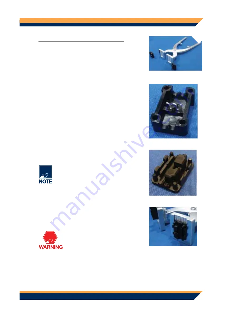
Open the tool and plates as shown prior to in-
1.
serting the top and bottom connectors
(Fig. 1)
.
Identify the top connector
2.
(Fig. 2)
.
Identify the bottom connector half
3.
(Fig. 3)
.
Note the hole location on the bottom con-
nector where the branch tracer wire will
be inserted.
Insert the top and bottom half connectors into
4.
the tool by sliding them completely into the
plate channels marked “Top” and “Bottom”.
Important note: The connector halves
must be inserted into their respec-
tive channels to attain the friction fit.
Additionally, the orientation of the
bottom connector is critical. The bottom
connector should be inserted with the
branch tracer wire hole opening oppo-
site the channel bottom
(Fig. 4)
.
Fig. 1
Fig. 2
Fig. 3
Fig. 4
TIMBERLINE TRTW1
5


