background image

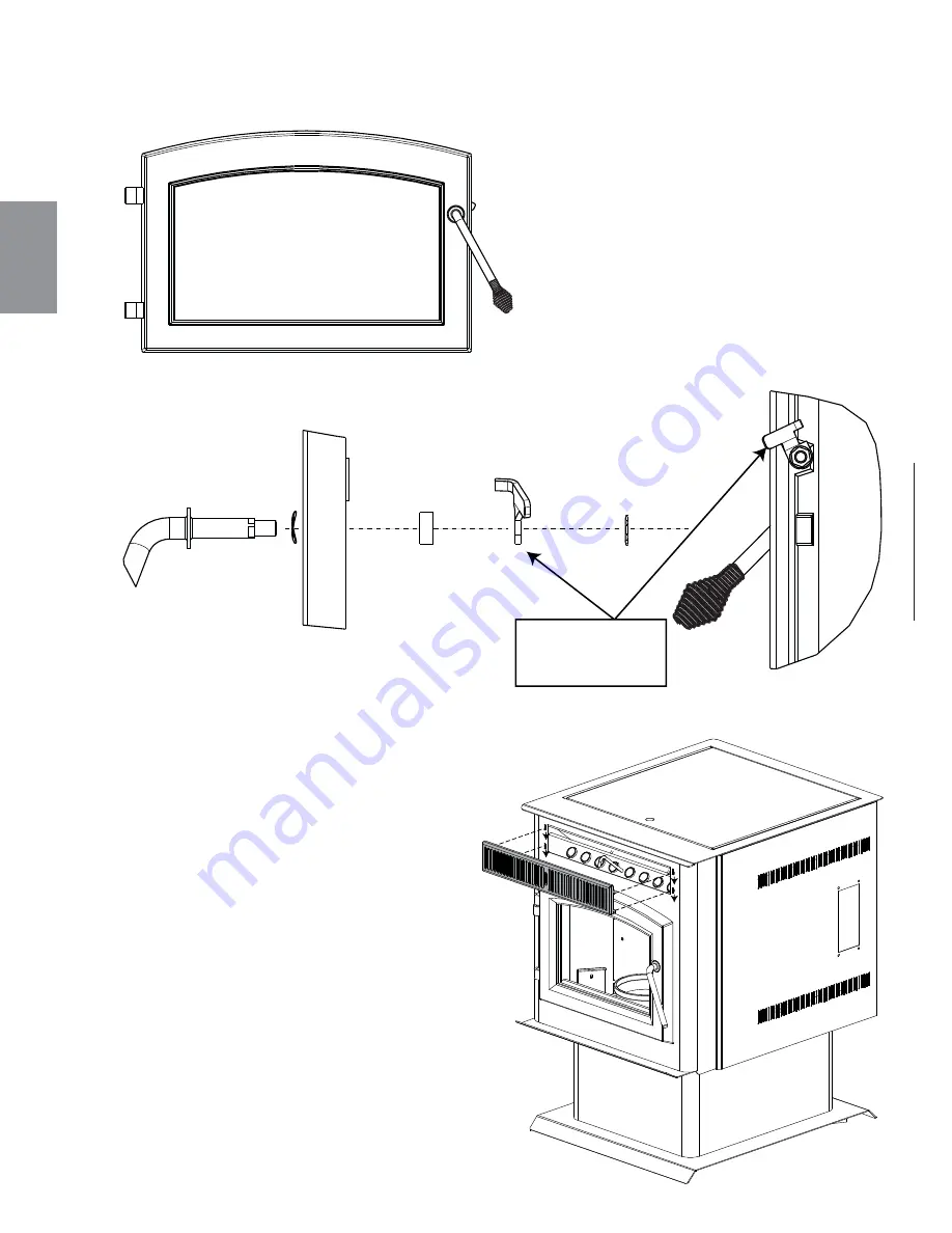
POIGNÉE 

DE PORTE

LOQUET DE POIGNÉE 

DE PORTE

ÉCROU DE

BLOCAGE

PORTE 

ESPACEUR

RONDELLE

 À RESSORT

VUE DE FACE

NOTE : Position du      
loquet de poignée 
de porte.

W415-1477 A / 10.19.16

74

FR

6.3 PANNEAU 

DÉCORATIF

6.2 

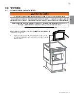
INSTALLATION DE LA POIGNÉE DE PORTE

Summary of Contents for TPI35

Page 1: ...fire department fire prevention bureau etc should be consulted before installation to determine the need to obtain a permit Contact local building or fire officials about restrictions and installation inspection requirements in your area This appliance is hot while in operation Keep children clothing and furniture away Contact may cause skin burns Do not start a fire with chemicals or fluids such ...

Page 2: ...1 HORIZONTAL TERMINATION THROUGH WALL 16 4 6 2 VERTICAL RISE HORIZONTAL TERMINATION THROUGH WALL 16 4 6 3 VERTICAL TERMINATION 17 4 6 4 CLASS A CHIMNEY RETROFIT 17 4 6 5 HEARTH MOUNT INSTALLATION 18 4 7 INSERT VENTING INSTALLATION EXAMPLES 19 4 7 1 TYPICAL EXISTING MASONRY INSTALLATION 19 4 7 2 FACTORY BUILT FIREPLACE 20 5 0 FRAMING INSERT ONLY 21 5 1 INSTALLATION INTO A COMBUSTIBLE ENCLOSURE 22 5...

Page 3: ...g plate see RATING PLATE INFORMATION section 1 1 STOVE 10 1 6 BURN POT CLEANING 35 10 2 BI WEEKLY OR EVERY 10 BAGS OF PELLETS 35 10 2 1 VACUUM FIREBOX 35 10 3 SEMI ANNUALLY OR EVERY TON OF PELLET 36 10 3 1 HOPPER CLEANING 36 10 3 2 SOOT AND FLY ASH FORMATION 36 10 3 3 VERTICAL EXHAUST DUCT CLEANING 36 10 3 4 EXHAUST BLOWER CLEANING 37 10 3 5 SEAL CHECK 37 10 3 6 VENT CLEANING 38 10 4 JAMMED AUGER ...

Page 4: ...Door see FINISHING INSTALLING THE VIEW ING DOOR section Venting see VENTING and INSTALLATION sections Handle see DOOR HANDLE INSTALLATION section Rating plate see RATING PLATE INFORMATION section Flashing see FLASHING INSTALLATION section ...

Page 5: ...ed or qualified service person The viewing door and ashpan must be closed and latched during operation Do not strike or slam shut the appliance glass door Only doors optional fronts certified with the unit are to be installed on the appliance Keep the packaging material out of reach of children and dispose of the material in a safe manner As with all plastic bags these are not toys and should be k...

Page 6: ...S section A B 305 16 770mm 211 4 540mm 1911 16 500mm 231 2 597mm 241 4 616mm 257 8 657mm 17 432mm 115 8 295mm CENTREOF AIRINTAKE CENTREOF EXHAUST 383 8 975mm 293 8 746mm 2013 16 529mm 71 8 181mm CENTREOF EXHAUST 17 8 47mm CENTREOF AIRINTAKE 81 2 220mm CENTREOFAIRINTAKE 55 8 143mm CENTREOFEXHAUST 11 4 32mm 383 8 975mm 211 4 540mm ...

Page 7: ...ING A B Adjustable Flashing 11 279mm to 13 330mm 10 1 2 267mm to 12 1 2 317mm Electrical Rating 115 Volts 3 6 Amps 60Hz Watts During Ignition Sequence 400 approximately Watts During Operation 180 approximately Weight Stove 158 lbs 1003kg Insert 140 lbs 889kg Exhaust Collar 3 76mm Intake Collar 2 51mm Hopper Capacity 45 Pounds 20kg Burn Rate 1 5 to 4 5 Pounds Per Hour 0 7 to 2 Kilograms Per Hour BT...

Page 8: ...These appliances are equipped with levelling screws that penetrate the front corners of the firebox If these screws are missing it will have a negative influence on the performance of this appliance Ensure that the levelling screws are tightened into position The protective wrap on plated parts is best removed when the assembly is at room temperature but this can be improved if the assembly is war...

Page 9: ...moisture of the pellets Store pellets in a cool dry area to prevent moisture absorption 64 1 WARNING IT IS IMPORTANT TO SELECT AND USE ONLY PELLETS THAT ARE DRY AND FREE OF DIRT OR ANY IMPURITIES SUCH AS HIGH SALT CONTENT DIRTY FUEL WILL ADVERSELY AFFECT THE OPERATION AND PERFORMANCE OF THE APPLIANCE AND WILL VOID THE WARRANTY THE PELLET FUEL INSTITUTE P F I HAS ESTABLISHED STANDARDS FOR WOOD PELL...

Page 10: ... CET APPAREIL À LA CHEMINÉE D UN AUTRE APPAREIL REMPLACER LA VITRE PAR UNE VITRE EN CÉRAMIQUE SEULEMENT DANGER RISQUE DE SECOUSSE ÉLECTRIQUE DÉBRANCHER L ALIMENTATION ÉLECTRIQUE AVANT DE PROCÉDER À L ENTRETIEN GARDER LA PORTE VITRÉE ET LA PORTE DU TIROIR À CENDRES BIEN FERMÉES DURANT LE FONCTIONNEMENT CONTACTER LES AUTORITÉS LOCALES DU BÂTIMENT ET DU SERVICE DES INCENDIES AU SUJET DES RESTRICTIONS...

Page 11: ...ee VENTING section Outside air see OUTSIDE AIR section Insert model To install as an insert into an existing masonry appliance or factory built appliance see VENTING section To install into a combustible enclosure see INSTALLATION INTO A COMBUSTIBLE ENCLOSURE section Have an authorized dealer install the appliance If you install the appliance yourself have your dealer review your installation plan...

Page 12: ...ALLATION DO NOT INSTALL INTO ANY AREA HAVING LESS THAN 48 1219mm CEILING TO APPLIANCE BOTTOM EXCLUDING HEARTH HEIGHT Through the Wall Vents complete with outside air Interior Vertical Vents NOTE If interior vertical pellet vent is used the clearance to the back wall is determined by the upward turning elbow or Tee It will vary in depth depending on the brand of pellet vent used it is approximately...

Page 13: ... vents must be made with 1 3 4 45mm diameter or larger metal or aluminum duct with a metal screen attached to the end to keep out rodents P V C or other materials may not be used The outside air inlet must not be above or within 12 305mm of the chimney termination must have a rain cap or down turned elbow to prevent the water from entering and be located so that it will not become plugged by snow ...

Page 14: ...nation must exhaust above the air inlet elevation and parallel or above the exhaust output of the pellet appliance It is recommended that at least 3 0 9m of vertical pipe be installed to create some natural draft This is to help prevent the possibility of smoke or odour entering the home during the appliance shut down or in the event of a power outage Horizontal sections must have a 1 4 6 4mm rise...

Page 15: ...orizontal distance of 2 feet 0 6m from the center line of the terminal D 0 0mm Clearance to an outside corner wall E 3 75mm Clearance to an inside combustible corner wall or protruding combustible obstructions vent chase etc F 9 22 9cm Clearance to a non mechanical air supply inlet to the building or a combustion air inlet to any other appliance G 3 0 9m Clearance to a mechanical air supply inlet ...

Page 16: ...um Wall Thimble Maximum Wall Thimble Outside Air Recommended Floor Protection 6 152mm Minimum 3 76mm 2 51mm 17 432mm 11 5 8 295mm 17 432mm 11 5 8 295mm 12 305mm 5 1 5m 4 6 STOVE VENTING INSTALLATION EXAMPLES 4 6 1 HORIZONTAL TERMINATION THROUGH WALL 4 6 2 VERTICAL RISE HORIZONTAL TERMINATION THROUGH WALL ...

Page 17: ...s Vertical Cap Roof Flashing Storm Collar Floor Protection 3 76mm 2 51mm 24 610mm 4 6 3 VERTICAL TERMINATION Class A Chimney Ceiling Support Outside air Recommended Installation show ing inlet of outside air in ventilated crawl space Vent must maintain 3 76mm clearance to combustibles Roof Flashing Storm Collar Floor Protection Vertical Cap 3 76mm 2 51mm 4 6 4 CLASS A CHIMNEY RETROFIT ...

Page 18: ...ded Floor Protection ended out Outside Air Recomme Storm Collar Vertical Cap Storm Collar Chimney Cap Bring outside air to the stove Pellet Liner Flue Cover Pellet Vent 6 152mm MIN 4 6 5 HEARTH MOUNT INSTALLATION For installation instructions See TYPICAL EXISTING MASONRY section ...

Page 19: ...ation If necessary have any repair work done by a qualified professional before installing the appliance A Remove the fireplace damper or fasten it permanently open B Measure the throat of the fireplace and mark this shape on a piece of 24 0 511mm gauge sheet metal flue cover Cut a hole sized for the pellet liner to lie directly below the fireplace flue opening Allow 2 50 8mm of material for a fla...

Page 20: ...before installing the appliance A Remove the fireplace damper or fasten it permanently open B Measure the throat of the fireplace and mark this shape on a piece of 24 0 511mm gauge sheet metal flue cover Cut a hole sized for the pellet liner to lie directly below the fireplace flue opening Allow 2 50 8mm of material for a flange on all sides and cut to these measurements Bend down the flanges If y...

Page 21: ...ING MATERIAL THICKNESS TO MAINTAIN CLEARANCES FRAMING OR FINISHING MATERIAL CLOSER THAN THE MINIMUMS LISTED MUST BE CONSTRUCTED ENTIRELY OF NON COMBUSTIBLE MATERIALS MATERIALS CONSISTING ENTIRELY OF STEEL IRON BRICK TILE CONCRETE SLATE GLASS OR PLASTERS OR ANY COMBINATION THEREOF ARE SUITABLE MATERIALS THAT ARE REPORTED AS PASSING ASTM E 136 STANDARD TEST METHOD FOR BEHAVIOUR OF MATERIALS IN A VER...

Page 22: ...stalling the insert as a built in appliance it is important to maintain the clearances to combustibles see MINIMUM CLEARANCE TO COMBUSTIBLES section A non combustible hearth must cover the flooring underneath as well as a minimum of six inches in front and to both sides of the appliance A Install floor protection B Frame structure maintaining minimum clearances Locate and frame openings for both the...

Page 23: ... 1 7 8 48mm 7 1 8 181mm 2 51mm MIN 5 3 MINIMUM CLEARANCE TO COMBUSTIBLES Side wall to appliance 8 203mm Mantel to top of appliance 8 203mm Top facing to appliance 6 3 8 162mm Side facing to appliance 6 152mm Floor protection 6 152mm Mantel Depth Length 10 254mm Side Wall 10 254mm Mantel 6 152mm 6 152mm 8 203mm MIN 8 203mm MIN 10 254mm Floor Protection Minimum 6 152mm in front of door and to either...

Page 24: ...APPLIANCE TO OVERHEAT ENSURE ALL CLEARANCES I E BACK SIDE TOP VENT MANTEL FRONT ETC ARE CLEARLY MAINTAINED WHEN USING PAINT OR LACQUER TO FINISH THE MANTEL THE PAINT OR LACQUER MUST BE HEAT RESISTANT TO PREVENT DISCOLOURATION 73 1 8 203mm 14 356mm 12 305mm 10 254mm 10 254mm 16 406mm MANTEL 14 356mm 12 305mm 35 889mm STOVE 48 1219mm 30 762mm Minimum Alcove Dimensions 5 5 MINIMUM STOVE ALCOVE INSTAL...

Page 25: ... of the appliance Lower into place until both bushings touch 6 1 VIEWING DOOR INSTALLATION WARNING GLASS MAY BE HOT DO NOT TOUCH GLASS UNTIL COOLED THE DOOR LATCHES ARE PART OF A SAFETY SYSTEM AND MUST BE PROPERLY ENGAGED DO NOT OPERATE THE APPLIANCE WITH LATCHES DISENGAGED BEFORE DOOR IS REMOVED TURN THE APPLIANCE OFF AND WAIT UNTIL APPLIANCE IS COOL TO THE TOUCH DOORS ARE HEAVY AND FRAGILE SO HA...

Page 26: ...0 19 16 26 EN 6 2 DOOR HANDLE INSTALLATION 6 3 DECORATIVE INSET DOOR HANDLE DOOR HANDLE LATCH LOCK NUT DOOR SPACER FRONT VIEW NOTE Position of door handle latch 98 1 NOTE DOOR MAY NOT BE AS ILLUSTRATED SPRING WASHER ...

Page 27: ...he top panel aligning the slots in the top panel with the holes in the side panel D Secure the top panel by to the side panels with the screws and washers provided NOTE Make sure the side panels are tight to the firebox before securing the screws E The flashing can be adjusted forward and backward by re adjusting the flashing along the magnets F Slide trim over flashing TOP PANEL TRIM LEFT SIDE LEFT ...

Page 28: ...IFIED ELECTRICIAN AND SHALL BE IN COMPLIANCE WITH LOCAL CODES IN THE ABSENCE OF LOCAL CODES USE THE CURRENT CSA22 1 CANADIAN ELECTRIC CODE IN CANADA OR THE CURRENT NATIONAL ELECTRIC CODE ANSI NFPA NO 70 IN THE UNITED STATES ALWAYS LIGHT THE PILOT WHETHER FOR THE FIRST TIME OR IF THE GAS SUPPLY HAS RUN OUT WITH THE GLASS DOOR OPENED OR REMOVED 69 2_2 HIGH LIMIT CONVECTION BLOWER IGNITOR POWER CORD ...

Page 29: ...l stay on until proof of fire determined by the appliance temperature At anytime during the ignition cycle once proof of fire is met the appliance goes into normal operating mode NOTE Flame should appear in the burn pot within 3 to 7 minutes from commencing the ignition cycle The ignition cycle should end in approximately 12 to 15 minutes At this point adjustments to feed rate can be made or the app...

Page 30: ... heat it will initiate an ignition cycle ON OFF Use this button to turn the appliance on and off HEAT LEVEL Pressing the heat level button will increase the heat level one setting Pressing the heat level button down will decrease the heat level one setting The red lights at the top left of the control will indicate the heat setting 1 through 3 PRIME Pressing and holding this button will turn the a...

Page 31: ... bottom light goes out BLOWER TRIM Similar to the feed rate it may be necessary to trim the speed of the combustion blower Due to specific installations it may be necessary to increase or decrease the amount of air moving through the burn pot to achieve maximum efficiency In order to adjust the blower trim you need access to the back of the control panel Start by either removing the side panel pedes...

Page 32: ...wn cycles are normal and are to be expected 8 7 THERMOSTAT INSTALLATION An optional millivolt thermostat is available to help keep the room temperature constant NOTE The thermostat must be installed by a qualified installer Disconnect the power supply Remove the right side panel to gain access to the rear of the control panel Strip and connect the two thermostat wires to the two screw terminals on...

Page 33: ... see MAKE SURE PELLETS ARE NOT PILING UP or CLEANING THE BURNPOT sections 40 3A 10 1 1 ASH DISPOSAL If the glass is not kept clean permanent discolouration and or blemishes may result Normal operation of your pellet appliance will produce a build up on the glass that should be wiped off daily However poor quality pellets or extended burning on the low setting will cause the glass to smoke up faste...

Page 34: ...IL APPLIANCE HAS COOLED COMPLETELY OR WEAR HEAT RESISTANT GLOVES WHEN CLEANING OR HANDLING THIS APPLIANCE WARNING If the flames seem to be coming only from the sides are orange black turn the appliance off and check for a build up of pellets If the pellets build up over the burn pot turn the pellet feed switch to OFF The most likely causes are A Feed rate has been set to maximum for an extended pe...

Page 35: ...cuum out the firebox Do not use a household vacuum to clean the appliance We recommend that you use a shop vacuum that is equipped with a fine dust filter or a vacuum specifically made for ashes and soot Using a vacuum which is not equipped with a fine dust filter may clog and disperse fly ash and soot into the room NOTE The appliance must be completely extinguished before you vacuum the appliance...

Page 36: ...strict the flow of the flue gases Incomplete combustion occuring during startup shutdown or incorrect operation of the room appliance will lead to some soot formation which will collect in the exhaust venting system The exhaust venting system should be inspected at least once every year to determine if cleaning is necessary 40 9 A Pivot the viewing door wide open B Remove the one screw on each exh...

Page 37: ...nd place it back on to the housing taking care that the side of the motor does not tear the gasket and then re attach the nuts 40 11 EXHAUST BLOWER EXHAUST HOUSING NUTS 10 3 5 SEAL CHECK Check for air leaks around the door glass and ash pan and replace gaskets as required Air leaks into the firebox will decrease the appliance s performance greatly leading to excessive soot inefficient burning and ...

Page 38: ...A 10 19 16 38 EN 10 3 6 VENT CLEANING 10 4 JAMMED AUGER Occasionally damp fuel or foreign objects could get jammed in the auger screw When this occurs it will be necessary to empty the hopper and or remove the auger screw from the hopper assembly Start by emptying the pellets from the hopper If it is necessary to remove the auger cotter pin start by removing both of the side panels and the rear pa...

Page 39: ...60 C 2 W660 0055 HIGH LIMIT SWITCH 200 F 93 C 3 W660 0056 VACUUM SWITCH 4 W325 0043 HANDLE SPRING 5 W195 0004 POWER CORD 6 W435 0019 AUGER MOTOR 7 PSCB CONVECTION BLOWER TPS35 7 PICB CONVECTION BLOWER TPI35 8 W062 0027 SER COMBUSTION BLOWER 9 W290 0111 COMBUSTION BLOWER MOUNTING GASKET 10 W290 0120 COMBUSTION BLOWER MOTOR MOUNTING GASKET 11 W290 0113 CONVECTION BLOWER GASKET 12 W570 0107 AUGER SCR...

Page 40: ...R CAPACITY FROM 45 LBS 20 4KG TO 100 LBS 45 4KG PELLETS STOVE ONLY 36 TI800 FLASHING KIT INCLUDES FLASHING SURROUND SMALL HOPPER DOOR 37 F50 THERMOSTATIC REMOTE 38 F50 6 BULK THERMOSTATIC REMOTE 39 270 PAINT THURMALOX BLACK 40 F45 ON OFF REMOTE 41 F45 6 BULK ON OFF REMOTE 20 10 11 7 2 1 9 8 6 23 3 31 16 25 22 29 32 31 25 35 28 21 12 14 15 4 23 13 36 ...

Page 41: ...is open Appliance ran out of fuel Circuit Shortage Wiring connection problems Burn pot is not placed properly Jammed auger shaft Poor pellet quality damp pellets Burn pot not positioned properly Defective temperature sensor Ensure appliance is plugged in and or power outlet does not have any issues Manually reset high limit switch Close hopper lid Turn off the appliance and load fuel Set desired s...

Page 42: ...d glow If it does not replace the igniter Check the voltage going to the igniter during startup The voltage should be running a full current 115V If the voltage is lower than the full current check the wiring If the wiring is fully functional replace the control board Replace affected gaskets Check if there are any holes or damages in the venting system If there is an issue seal the vents properly...

Page 43: ... therefore leaving the fuel completely unburned in the burn pot This will cause the fuel to burn cold and very slowly Fuel also may build up and smother the fire NOTE The appliance may require a change to the vent system or installation of fresh air to correct air to fuel ratio problems Temporarily by pass the low limit switch by disconnecting the two wires and connecting them together with a short...

Page 44: ...o low Dark colour build up on glass Unhook the hose form the vacuum switch and blow through it If air will not flow through the hose use a wire coat hanger to clear blockage Follow all the cleaning procedures in the maintenance section Ensure the door is closed and gaskets are in good shape If not replace gaskets Check the connectors that attach the blue wires to the vacuum switch Check power going...

Page 45: ...systems such as exhaust blowers furnaces clothes dryers etc Any damages to appliance combustion chamber heat exchanger or other components due to water weather damage long periods of dampness condensation damaging chemicals or cleaners will not be the responsibility of Wolf Steel Regular cleaning of the fine ash generated during the operation of this appliance is a necessary part of maintaining yo...

Page 46: ...W415 1477 A 10 19 16 46 EN 43 1 14 0 SERVICE HISTORY ...

Page 47: ...W415 1477 A 10 19 16 47 EN 44 1 15 0 NOTES ...

Page 48: ...MT t 8PPE 4UPWFT FBUJOH PPMJOH t MFDUSJD JSFQMBDFT t 0VUEPPS JSFQMBDFT t BT SJMMT JSFQMBDFT FBUJOH PPMJOH DBMM t SJMMT DBMM napoleonproducts com BQPMFPO 3PBE BSSJF 0OUBSJP BOBEB BZWJFX SJWF BSSJF 0OUBSJP BOBEB JMMFS SJWF SJUUFOEFO FOUVDLZ 64 5SBOT BOBEB JHIXBZ POUSFBM 2VFCFD BOBEB 5 ...

Page 49: ...fonctionne Tenir les enfants les vêtements et les meubles à l écart Le contact peut causer des brûlures N allumez pas votre feu avec des produits chimiques ou des liquides tels que de l essence de l huile à moteur etc Ne brûlez pas de déchets des résidus de tonte de pelouse de caoutchouc des produits pétroliers résiduels de la peinture ou du diluant de solvants de plastique des matériaux contenant...

Page 50: ... EXISTANT 67 4 7 2 FOYER PRÉFABRIQUÉ 68 5 0 OSSATURE ENCASTRÉ SEULEMENT 69 5 1 INSTALLATION DANS UNE ENCEINTE COMBUSTIBLE 70 5 2 DÉGAGEMENTS MINIMAUX DE L ENCEINTE 71 5 3 DÉGAGEMENTS MINIMAUX AUX MATÉRIAUX COMBUSTIBLES 71 5 4 DÉGAGEMENTS MINIMAUX DE LA TABLETTE 72 5 5 EXIGENCES MINIMALES DE L INSTALLATION DANS UNE ALCÔVE 72 6 0 FINITIONS 73 6 1 INSTALLATION DE LA PORTE VITRÉE 73 6 2 INSTALLATION D...

Page 51: ...ETIEN 93 Porte voir la section FINITION INSTALLATION DE LA PORTE VITRÉE Évacuation voir les sections ÉVACUATION GÉNÉRALE et INSTALLATION Plancher voir la section PLANIFICATION DE L INSTALLATION PROTECTION DU PLANCHER Voir la section PRISE D AIR EXTÉRIEUR Poignée voir la section INSTALLATION DE LA POIGNÉE DE PORTE Plaque d homologation voir la section INFORMATION SUR LA PLAQUE D HOMOLOGATION 1 1 PO...

Page 52: ...NSTALLATION DE LA PORTE VITRÉE Évacuation voir les sections ÉVACUATION et INSTALLATION Poignée voir la section INSTALLATION DE LA POIGNÉE DE PORTE Plaque d homologation voir la section INFORMATION SUR LA PLAQUE D HOMOLOGATION Contour voir la section INSTALLATION DU CONTOUR ...

Page 53: ...ors de la portée des enfants et mettez ces matériaux au rebut de façon sécuritaire Comme tous les emballages de plastique ces matériaux ne sont pas des jouets et doivent demeurer hors de la portée des enfants et des bébés Si cet appareil n est pas installé de façon adéquate un incendie pourrait s ensuivre N exposez pas l appareil aux éléments c à d la pluie etc et gardez le au sec en tout temps De...

Page 54: ... 975mm 293 8 746mm 2013 16 529mm 71 8 181mm 17 8 47mm 81 2 220mm 55 8 143mm 11 4 32mm 383 8 975mm 211 4 540mm CENTREDU CONDUIT D ÉVACUATION CENTREDE LAPRISED AIR CENTREDELAPRISED AIR CENTREDUCONDUIT D ÉVACUATION W415 1477 A 10 19 16 54 FR 2 1 1 POÊLE 2 1 2 ENCASTRÉ AVEC CONTOUR A et B sont réglables voir la section SPÉCIFICATIONS 2 1 DIMENSIONS ...

Page 55: ...330mm 10 1 2 267mm à 12 1 2 318mm Spécifications électriques 115 Volts 3 6 Amps 60Hz Watts durant la séquence d allumage 400 approximativement Watts durant le fonctionnement 180 approximativement Poids Poêle 158 lb 1003kg Encastré 140 lb 889kg Collet d évacuation 3 76mm Collet de prise d air 2 51mm Capacité du réservoir 45 livres 20kg Taux de combustion 1 5 à 4 5 livres par heure BTU Hr 12 750 à 3...

Page 56: ...s de l avant du foyer Si ces vis manquent il aura une influence négative sur le fonctionnement de cet appareil Assurez vous que les vis nivelant sont resserrées en place L emballage de protection sur les pièces plaquées s enlève mieux lorsque l assemblage est à température ambiante ou lorsqu il est chauffé avec un séchoir à cheveux ou une autre source de chaleur similaire Si l appareil est install...

Page 57: ...e brûler des combustibles de moins bonne qualité Ne brûlez pas d autres types de granules agricoles ou sous produits luzerne noyaux de cerise noyaux d olive coquilles de noix etc puisqu il est interdit de les brûler dans cet appareil Le maïs ne doit pas contenir de saletés ni de débris Ne brûlez jamais du maïs fraîchement récolté Les dommages causés par du maïs avec des saletés ne sont pas couvert...

Page 58: ...st Protection de plancher Évents Verticaux Intérieurs Té 3 6 6 45 2 2 6 2 2 3 2 6 6 6 6 6 9700539 WSL 4001657 NGZ 4001658 NAC 4001659 WUSA U S Environmental Protection Agency Certifié conforme à la norme d émanation de particles de 2015 Non approuvé pour la vente après le 15 mai 2020 40 CFR Part 60 Subpart AAA 3 3 Grammes par heure U S ENVIRONMENTAL PROTECTION AGENCY Certified to comply with 2015 ...

Page 59: ...oêle localisez les montants du mur pour des évacuations horizontales Vous devrez possiblement ajuster la position du poêle afin que l évent ne passe pas au même niveau qu une pièce de charpente Le poêle doit être positionné de façon à ce qu aucun article combustible soit placé ou puisse pivoter p ex rideaux portes à moins de 48 1219 2mm de la face vitrée du poêle 67 1B W415 1477 A 10 19 16 59 FR P...

Page 60: ... APPAREIL EXCLUANT LA HAUTEUR DE L ÂTRE AVERTISSEMENT Installations à travers un mur avec prise d air extérieur 3 4 DÉGAGEMENTS MINIMAUX AUX MATÉRIAUX COMBUSTIBLES 3 4 1 INSTALLATION DROITE NOTE Si vous utilisez des évents verticaux intérieurs le dégagement au mur arrière est calculé à partir du raccord en T Le dégagement variera selon la marque du système d évents environ 5 127mm Avant de placer ...

Page 61: ... appareil a été conçu et testé de sorte que le plancher ne surchauffera pas même sans protection Référez vous aux codes du bâtiment locaux pour des matériaux de protection de plancher adéquats 3 5 PROTECTION DE PLANCHER Disponible auprès de votre détaillant autorisé 114KT L air extérieur ne doit pas provenir d un endroit fermé tel qu un garage ou un espace réduit non ventilé NOTE Wolf Steel ltée s...

Page 62: ...ions du système d évacuation afin de faciliter l accès lors de l entretien 5 1 5m 10 3 1m 15 4 6m 20 6 1m 33 10 1m 30 9 1m 25 7 6m 0 5 1 5m 10 3 1m 0 Utilisez un évent de type L de 4 102mm de diamétre lorsque l évacuation se situe à cette hauteur Utilisez un évent de type L de 3 76mm ou de 4 102mm de diamétre lorsque l évacuation se situe à cette hauteur AVERTISSEMENT CONSERVEZ TOUJOURS UNE DISTAN...

Page 63: ...e verticale de moins de 15 pieds 13 7m au dessus de l ensemble de régulateur compteur Dégagement horizontal de chaque côté depuis la ligne verticale tirée du centre d un ensemble de régulateur compteur de gaz naturel ou de propane ou d un système d évacuation mécanique Recommandé an de prévenir la formation de buée dans les fenêtres et les cassures thermiques Ceci est une distance recommandée Véri...

Page 64: ...otection de plancher Prise d air extérieur Recommandée Prise d air extérieur Recommandée Coupe feu mural Coupe feu mural W415 1477 A 10 19 16 64 FR 4 6 1 TERMINAISON HORIZONTALE À TRAVERS UN MUR 4 6 2 COURSE VERTICALE ET TERMINAISON HORIZONTALE À TRAVERS UN MUR 4 6 EXEMPLES D INSTALLATION D ÉVACUATION ...

Page 65: ...entrée d air dans un espace réduit ventilé Support à plafond pour cheminée de type A Prise d air extérieur Recommandée Illustré l entrée d air dans un espace réduit ventilé L évacuation doit con server un dégagement de 3 76mm aux matériaux combustibles Solin de toit Collet de solin Protection de plancher Chapeau 3 76mm 2 51mm W415 1477 A 10 19 16 65 FR 4 6 3 TERMINAISON VERTICALE 4 6 4 INSTALLATIO...

Page 66: ...et de solin Protection de plancher Chapeau de cheminée Té de nettoyage Couvercle du carneau Évacuation Acheminez l air extérieur au poêle Prise d air extérieur Recommandée W415 1477 A 10 19 16 66 FR 4 6 5 INSTALLATION DANS UNE CHEMINÉE DE MAÇONNERIE ...

Page 67: ...nt d installer l encastré A Retirez le registre du foyer ou attachez le de façon permanente en position ouverte B Mesurez la gorge du foyer puis tracez sa forme sur un morceau de tôle de calibre 24 couvercle de carneau Découpez un trou équivalant au diamètre du conduit d évacuation de l encastré afin qu il re pose directement sous l ouverture du carneau du foyer Allouez un surplus de 2 50 8mm de m...

Page 68: ...rcle de carneau Découpez un trou équivalant au diamètre du conduit d évacuation de l encastré afin qu il re pose directement sous l ouverture du carneau du foyer Allouez un surplus de 2 50 8mm de matériel de tous les côtés pour les brides et découpez selon ces dimensions Pliez les brides vers le bas Si c est la première fois que vous faites ceci il serait bon de faire d abord un modèle en carton e...

Page 69: ...N COMBUSTIBLES LES MATÉRIAUX FAITS ENTIÈREMENT D ACIER DE FER DE BRIQUE DE TUILE DE BÉTON D ARDOISE DE VERRE OU DE PLÂTRE OU D UNE COMBI NAISON DE CES MATÉRIAUX SONT APPROPRIÉS LES MATÉRIAUX RÉPONDANT À LA NORME ASTM E 136 MÉTHODE DE TEST STANDARD DU COMPORTEMENT DES MATÉRIAUX DANS UNE FOURNAISE AVEC TUBE VERTICAL À 1382 F 750 C ET À LA NORME UL763 SONT CONSIDÉRÉS COMME ÉTANT DES MATÉRIAUX NON COM...

Page 70: ...tection incombustible doit recouvrir le plancher situé en dessous de même que dépasser d au moins six pouces sur le devant et de chaque côté de l appareil A Installez la protection de plancher B Encadrez la structure en respectant les dégagements minimaux Localisez et encadrez les ouvertures de l évacuation et de la prise d air Une prise d air extérieur est obligatoire dans le cas des installation...

Page 71: ... 6 152mm 6 152mm 8 203mm MIN W415 1477 A 10 19 16 71 FR Du mur latéral à l appareil 8 203mm De la tablette au dessus de l appareil 8 203mm De la façade supérieure à l appareil 6 3 8 162mm De la façade latérale à l appareil 6 152mm Protection de plancher 6 152mm Profondeur de la tablette 10 254mm 5 2 DÉGAGEMENTS MINIMAUX DE L ENCEINTE 5 3 DÉGAGEMENTS MINIMAUX AUX MATÉRIAUX COMBUSTIBLES Protection d...

Page 72: ... RESPECTÉS À LA LETTRE LORSQUE VOUS UTILISEZ DE LA PEINTURE OU DU VERNIS COMME FINITION POUR VOTRE TABLETTE ASSUREZ VOUS QU ILS SOIENT RÉSISTANTS À LA CHALEUR AFIN DE PRÉVENIR LA DÉCOLORATION 73 1 8 203mm 14 356mm 12 305mm 10 254mm 10 254mm 16 406mm TABLETTE 14 356mm 12 305mm W415 1477 A 10 19 16 72 FR 35 889mm 48 1219mm 30 762mm POÊLE Dimensions minimales de l alcôve 5 5 EXIGENCES MINIMALES DE L ...

Page 73: ...ANT D ENLEVER LA PORTE ÉTEIGNEZ L APPAREIL ET ATTENDEZ QUE CE DERNIER SOIT FROID AU TOUCHER LES PORTES SONT LOURDES ET FRAGILES MANIPULEZ AVEC SOIN 75 2 W415 1477 A 10 19 16 73 FR La porte vitrée a été emballée à part mais elle DOIT être installée avant de faire fonctionner l appareil A Alignez les tiges sur la porte avec les bagues du côté gauche de l appareil abaissez la porte jusqu à ce que les...

Page 74: ...QUET DE POIGNÉE DE PORTE ÉCROU DE BLOCAGE PORTE ESPACEUR RONDELLE À RESSORT VUE DE FACE NOTE Position du loquet de poignée de porte W415 1477 A 10 19 16 74 FR 6 3 PANNEAU DÉCORATIF 6 2 INSTALLATION DE LA POIGNÉE DE PORTE ...

Page 75: ...e combustion par les trois aimants situés de chaque côté C Descendez le panneau supérieur en alignant les fentes du panneau supérieur avec les trous du panneau latéral D Fixez le panneau supérieur aux panneaux latéraux à l aide des vis et des rondelles fournies NOTE Assurez vous que les panneaux latéraux sont bien fixés à la chambre de combustion avant de serrer les vis E Un ajustement du contour ...

Page 76: ...BSENCE DE CODES LOCAUX UTILISEZ LA VERSION COURANTE DU CODE CANADIEN DE L ÉLECTRICITÉ CSA C22 1 AU CANADA OU LE NATIONAL ELECTRICAL CODE ANSI NFPA 70 AUX ÉTATS UNIS ALLUMEZ TOUJOURS LA VEILLEUSE QUE CE SOIT POUR LA PREMIÈRE FOIS OU LORSQUE L APPROVISIONNEMENT EN GAZ EST ÉPUISÉ AVEC LA PORTE VITRÉE OUVERTE OU RETIRÉE 69 2 W415 1477 A 10 19 16 76 FR SURCHAUFFE VENTILATEUR DE CONVECTION ALLUMEUR CORD...

Page 77: ...ns une inspection PRÉCOMBUSTION pour faire évaporer les odeurs associées à la première combustion Si possible placez l appareil à l extérieur et chargez cinq livres de granules dans le réservoir Branchez le cordon d alimentation dans une prise de courant murale ordinaire L appareil est muni d un tableau de contrôle qui a été livré en mode manuel La première fois que vous démarrez un nouvel apparei...

Page 78: ...il amorce un cycle de démarrage ON OFF Utilisez ce bouton pour allumer et éteindre l appareil CHALEUR HEAT Appuyer sur la flèche HEAT pointant vers le haut augmentera le niveau de chaleur d un réglage Appuyer sur la flèche HEAT pointant vers le bas diminuera le niveau de chaleur d un réglage Les voyants rouges dans la partie supérieure gauche du contrôle indiqueront le réglage de la chaleur de 1 à 3...

Page 79: ...n niveau 1 le temps entre les cycles d alimentation de la vis sans fin NOTE Le voyant qui n est pas allumé indique le réglage de l appareil bas neutre ou élevé RÉGLAGE DE LA SOUFFLE RIE BORNES À VIS CHALEUR HEAT CHALEUR HEAT CHALEUR HEAT PRÉRÉGLAGES EN USINE PLUS CARBURANT MOINS CARBURANT BOUTON D AMORÇAGE BOUTON D AMORÇAGE BOUTON D AMORÇAGE RÉGLAGE DE LA SOUFFLERIE Tout comme la vitesse d alimenta...

Page 80: ...tre perceptible lorsque les gran ules sont achemi nés dans le brûleur W415 1477 A 10 19 16 80 FR Un thermostat millivolt optionnel est disponible pour vous aider a garder la température de la pièce constante NOTE Le thermostat doit être installé par un installateur qualifié Débranchez l alimentation électrique Enlevez le panneau latéral droit pour avoir accès à l arrière du panneau de commande Dén...

Page 81: ... appareil est muni de pièces plaquées vous devez nettoyer les empreintes de doigts ou toute autre marque sur les surfaces plaquées avant d utiliser l appareil pour la première fois Utilisez un nettoyant pour vitre ou du vinaigre et un linge pour nettoyer Si les pièces ne sont pas bien nettoyées avant la première utilisation les marques peuvent rester en permanence sur le placage Après que le placa...

Page 82: ... CE POÊLE AVERTISSEMENT TIGE DE NETTOYAGE DE L ÉCHANGEUR DE CHALEUR Si les flammes semblent provenir seulement des côtés ou si leur couleur est orange foncé éteignez le poêle et vérifiez pour des accumulations de granules Si les granules s accumulent au dessus du brûleur tournez l alimentation en granules à OFF Les causes les plus probables sont A Le taux d alimentation a été réglé au maximum pour...

Page 83: ... JAMAIS DE GRANULES BRÛLANTS CHAMBRE DE COMBUSTION BOÎTIER D APPORT D AIR Plus vous nettoyez les cendres fines fréquemment plus votre appareil brûlera efficacement A Ouvrez la porte vitrée B Retirez le brûleur en le soulevant et placez le sur une surface incombustible C Passez l aspirateur dans la chambre de combustion N utilisez pas un aspirateur ménager pour nettoyer l appareil Nous vous conseil...

Page 84: ...u fond doivent être enlevés afin d éviter des accumulations excessives 40 8B A Ouvrez la porte vitrée complètement B Enlevez la vis sur chaque orifice d évacuation situé dans la chambre de combustion Enlevez les portes des orifices d évacuation et placez les sur une surface incombustible Insérez le boyau de l aspirateur dans les orifices d évacuation et aspirez le maximum de cendres fines qui se t...

Page 85: ...s 40 11 VENTILATEUR D ÉVACUATION BOÎTIER D ÉVACUATION ÉCROUS Vérifiez pour des fuites d air autour de la porte de la vitre et du tiroir à cendres puis replacez les joints plats tel qu exigé Les fuites d air à l intérieur de la chambre de combustion diminueront considérablement la performance du poêle cau sant une suie excessive une combustion inefficace et possiblement un mauvais fonctionnement de...

Page 86: ...es tels des bavures des endroits rugueux ou des cou pures dans le métal qui auraient pu causer un blocage 40 14A DÉBRANCHEZ LE CORDON D ALIMENTATION AVANT D EFFECTUER UN ENTRETIEN AVERTISSEMENT Le système d évacuation doit être nettoyé en utilisant des brosses à cheminée Nous recommandons que ce soit fait par un ramoneur qualifié 40 13A Les cendres fines se déposeront sur les sections horizontales...

Page 87: ...EUT CAUSER DES DOMMAGES MATÉRIELS OU DES BLESSURES CORPORELLES AVERTISSEMENT W415 1477 A 10 19 16 87 FR COMPOSANTS COMMUNS RÉF N DE PIÈCE DESCRIPTION 1 W660 0052 INTERRUPTEURDEBASSETEMPÉRATURE140 F 80 C 2 W660 0055 INTERRUPTEUR DE SURCHAUFFE 200 F 93 C 3 W660 0056 INTERRUPTEUR DE PRESSION 4 W325 0043 POIGNÉE À RESSORT 5 W195 0004 CORDON D ALIMENTATION 6 W435 0019 MOTEUR DE VIS SANS FIN 7 PSCB VENT...

Page 88: ...TÉLÉCOMMANDE THERMOSTATIQUE 38 F50 6 PAQUET DE TÉLÉCOMMANDES THERMOSTATIQUES 39 270 PEINTURE THURMALOX NOIRE 40 F45 TÉLÉCOMMANDE MARCHE ARRÊT 41 F45 6 PAQUET DE TÉLÉCOMMANDES MARCHE ARRÊT 20 10 11 7 2 1 9 8 6 23 3 31 16 25 22 29 32 31 25 35 28 21 12 14 15 4 23 13 36 COMPOSANTS COMMUNS RÉF N DE PIÈCE DESCRIPTION 28 W715 0843 SER PANNEAU DÉCORATIF 29 W225 0258 PORTE NOIRE 30 W430 0013 AIMANTS DE POR...

Page 89: ... tension de l allumeur durant l allumage Elle devrait être au maximum 115 volts Si la tension est moins que le maximum vérifiez le filage Si le filage est correct cela signifie que le tableau de commande est défectueux Contactez votre détaillant pour un appel de service La pièce est enfumée Vérifiez tous les joints d étanchéité Assurez vous que tous les raccords d évacuation sont scellés Panne de coura...

Page 90: ... tourne pas assez rapidement pour générer l aspiration adéquate dans la chambre de combustion Faites une inspection visuelle pour voir si le moteur tourne Vérifiez les niveaux de pression dans le canal d évacuation en contournant l interrupteur de pression puis retirez le boyau d évacuation de l interrupteur à pression Lorsque vous vérifiez la pression d évacuation placez l extrémité ouverte du boya...

Page 91: ...ant avec un petit morceau de fil Rebranchez ensuite l appareil S il fonctionne vous devez remplacer l interrupteur de basse température Ceci sert à des fins de test NE LAISSEZ PAS L INTERRUPTEUR CONTOURNÉ Si vous laissez l interrupteur contourné vos ventilateurs ne s éteindront jamais et si le feu s éteint la vis sans fin continuera l alimentation en granules jusqu à ce que le réservoir se vide Si le...

Page 92: ...s composants par l eau les dommages causés par les intempéries de longues périodes d humidité la condensation des produits chimiques ou produits d entretien nuisibles ne seront pas la responsabilité de Wolf Steel Le nettoyage régulier de la fine cendre générée durant le fonctionnement de cet appareil est nécessaire au bon entretien de votre appareil Tout dommage aux composants qui est attribuable à...

Page 93: ...èmes particuliers Travail effectué Nom du technicien Détaillant Historique d entretien de l appareil Cet appareil doit être entretenu annuellement selon son usage W415 1477 A 10 19 16 93 FR 14 0 HISTORIQUE D ENTRETIEN ...

Page 94: ...W415 1477 A 10 19 16 94 FR 44 1 15 0 NOTES ...

Page 95: ...W415 1477 A 10 19 16 95 FR 44 1 ...

Page 96: ...FBV 1PÐMFT Ë CPJT t 1SPEVJUT 7 t PZFST ÏMFDUSJRVFT t PZFST FYUÏSJFVST t SJMT Ë HB EF RVBMJUÏ PZFST IBVGGBHF FU MJNBUJTBUJPO SJMT DPNQPTF napoleonproducts com 3PVUF 5SBOTDBOBEJFOOF POUSÏBM 2VÏCFD 5 BQPMFPO 3PBE BSSJF 0OUBSJP BOBEB BZWJFX SJWF BSSJF 0OUBSJP BOBEB JMMFS SJWF SJUUFOEFO FOUVDLZ 64 ...

Reviews: