background image

TIMBERWOLF

TW 150DHB

30

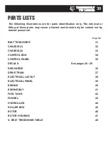
The following illustrations are for parts identification only. The removal or

fitting of these parts may cause a hazard and should only be carried out by

trained personnel. 

PARTS LISTS

Page No.

BELT TENSIONER

31

CHASSIS (1)

32

CHASSIS (2)

33

CONTROL BOX

34

CONTROL PANEL

35

DECALS                                                                           See pages 24 - 25
DISCHARGE

36

DRIVE TRAIN

37

ELECTRICAL LAYOUT

38

ELECTRICAL PANEL

39

ENGINE   

40

ENGINE BAY

41

FUEL TANK

42

FUNNEL

43

HYDRAULICS 

44

ROLLER BOX

45

ROTOR

46

ROTOR HOUSING

47

V- BELT TENSIONING TABLE

48

Summary of Contents for TW150DHB

Page 1: ...ndicator 10 Daily Checks Before Starting 10 Before Using the Chipper 11 Starting the Engine 11 Stopping the Engine 11 Discharge Controls 11 Starting to Chip 12 Chipping 12 Blockages 12 SERVICE INSTRUCTIONS 13 Service Schedule 14 Safe Maintenance 15 Safe Lifting of the Chipper 15 Spares 15 Battery Removal and Maintenance 15 Copper Ease Safety Information 16 Battery Safety Information 16 Change Blad...

Page 2: ... machine especially safe working practices Timberwolf s policy of regularly reviewing and improving their products may involve major or minor changes to the chippers or their accessories Timberwolf reserves the right to make changes at any time without notice and without incurring any obligation Due to improvements in design and performance during production there may be in some cases minor discre...

Page 3: ...m with feed tray folded 1400m m TIMBERWOLF TW 150DHB SPECIFICATION Engine type Kubota 4 cylinder diesel Maximum power 26kW 35hp Cooling method Water cooled Overall weight 737kg Starting method Electric Roller feed Twin hydraulic motors Maximum diameter material 150mm 6 Fuel capacity 18 litres Hydraulic oil capacity 15 litres Material processing capacity up to 4 tonnes hr Fuel type Diesel The Timbe...

Page 4: ...HARGE TUBE SPARE WHEEL CLAMP NUTS LIGHT BOARD CONTROL BOX BATTERY TOOL BOX ROLLER BOX COVER SIDE PANELS HYDRAULIC OIL FILTER REFLECTORS TIMBERWOLF TOW HEAD ANTI TRAP BAR ROTOR HOUSING REFLECTOR TW 150DHB RAIN FLAP TIMBERWOLF TW 150DHB 3 PARTS LOCATOR ...

Page 5: ...R FAN SECTION x2 ROTOR PULLEY DRIVE PULLEY BELT TENSION ADjUSTER FUEL PUMP EXHAUST FUEL FILTER CUTTER BLADE x2 DIP STICK OIL FILTER ALTERNATOR CONTROL PANEL STARTER MOTOR RADIATOR AIR FILTER HYDRAULIC PUMP DIRECTIONAL CONTROL VALVE TIMBERWOLF TW 150DHB 4 PARTS LOCATOR ...

Page 6: ...funnel the brash may push you to one side causing danger Badly twisted brash should be trimmed before being chipped to avoid thrashing in the feed funnel BE AWARE that the chipper can eject chips out of the feed funnel with considerable force Always wear full head and face protection ALWAYS work on the side of the machine furthest from any local danger e g not road side WARNING SAFE WORKING The ch...

Page 7: ... maintenance of any kind or whenever the machine is to be left unattended ALWAYS check the machine is well supported and cannot move ALWAYS operate the chipper with the engine set to maximum speed when chipping ALWAYS check visually for fluid leaks ALWAYS take regular breaks Wearing personal protective equipment for long periods can be tiring and hot ALWAYS keep hands feet and clothing out of feed...

Page 8: ...quality ear protection 93 3 dB 95 2 dB 96 3 dB 96 6 dB R 4 metres Guaranteed Sound Power 120dB A 101 5 dB 96 8 dB As required by Annex III of Directive 2000 14 EC Noise Emission in the environment by equipment for use outdoors R 10 metres 9 0 8 d B C a l c u l a t e d 90 8dB Cal c u l a t e d 90 8dB Calcul a t e d SAFE WORKING NOISE TEST MACHINE TW 150DHB NOTES Tested chipping 120mm x 120mm corsic...

Page 9: ...brake should be released and the prop stand and jockey wheel stored in the towing position a ENSURE the chipper will not roll away after being disconnected from the vehicle DISCONNECT the electrical cable from the vehicle socket RELEASE breakaway cable RELEASE the jockey wheel assembly clamp LOWER the jockey wheel assembly fully RETIGHTEN the jockey wheel assembly clamp WIND the jockey wheel assem...

Page 10: ...tons RED SAFETY BAR TEST To ensure the safety bar is always operational it must be activated once before each work session The rollers will not function until the bar is activated This procedure must be repeated each time the ignition is switched off GREEN BUTTON Forward feed Push the button once this activates the rollers and will allow you to start chipping if the rotor speed is high enough RED ...

Page 11: ...d on page 11 CHECK visually for fluid leaks CHECK fuel and hydraulic oil levels For parts location see diagrams on pages 3 4 AUTO CONTROLS EMERGENCY STOPPING ENGINE CONTROLS HYDRAULIC OIL LEVEL INDICATOR DAILY CHECKS BEFORE STARTING OPERATING INSTRUCTIONS 0 1 2 HOURS 0 0 0 0 0 0 0 BLADE WEAR The most important part of using a wood chipper is keeping the cutter blades sharp Timberwolf chipper blade...

Page 12: ...t of safe working BUCKET ANGLE 4 Adjust the bucket to the desired angle using the handle provided MOvE the throttle lever to the Tortoise to reduce the engine speed to idle LEAvE the engine running for 1 minute TURN the power switch to position 0 The engine should stop after a few seconds REMOvE the ignition key For more detailed information refer to the Engine Owner s Manual 3 6 4 5 7 1 2 PRESS T...

Page 13: ...ed funnel PROCEED to feed material into the feed funnel STARTING TO CHIP CHIPPING BLOCKAGES OPERATING INSTRUCTIONS WARNING Do not use or attempt to start the chipper without the protective guarding and discharge unit securely in place Failure to do so may result in personal injury or loss of life Wood up to the recommended diameter can be fed into the feed funnel Put the butt end in first and enga...

Page 14: ...L SERvICE AND MAINTENANCE OF TIMBERWOLF WOOD CHIPPERS YOU ARE STRONGLY ADvISED TO TAKE YOUR CHIPPER TO AN AUTHORISED AGENT FOR ALL BUT THE MOST ROUTINE MAINTENANCE AND CHECKS TIMBERWOLF ACCEPTS NO RESPONSIBILITY FOR THE FAILURE OF THE OWNER USER OF TIMBERWOLF CHIPPERS TO RECOGNISE GENERALLY ACCEPTED STANDARDS OF ENGINEERING MECHANICAL MAINTENANCE AND APPLY THEM THROUGHOUT THE MACHINE THE FAILURE T...

Page 15: ...ü Check fuel pipes and clamp bands ü Check battery electrolyte level ü Check for loose electrical wiring ü Replace hydraulic oil filter every year or 100 hours after service or repair work to the hydraulic system ü ü Replace hydraulic oil ü ü Replace fuel pipes and clamp bands Check coolant Change engine oil Replace engine oil filter cartridge Check valve clearance Replace anvils when worn Axle ma...

Page 16: ...rque Nm Blade Bolts M10 Standard T50 Torx 45 61 Hyd Motor Retaining Nuts M10 Standard 17mm Hex 34 46 Funnel Retaining Nuts M12 Standard 17mm Hex 38 51 General M8 Standard 13 mm Hex 17 23 General M10 Standard 17 mm Hex 34 46 General M12 Standard 19 mm Hex 60 80 Drain Bung in Fuel Tank 3 8 BSP 22 mm Hex 25 33 8 The lifting eye is designed to lift the machine s weight only Do not use hoist hook direc...

Page 17: ...er dispose of old batteries in household waste Product name Copper Ease Copper Ease contains no hazardous ingredients at or above regulatory disclosure limits however safety precautions should be taken when handling use of oil resistant gloves and saftey glasses are recommended respiratory protection is not required Avoid direct contact with the substance and store in a cool well ventilated area a...

Page 18: ...he negative terminal first Ensure good ventilation Use suitable direct current chargers only Connect the positive terminal of the battery to the positive output of the charger Connect the negative terminal accordingly Switch on the charger only after the battery has beenconnected and switch off the charger first after charging has been completed Charging current recommendation 1 10 ampere of the b...

Page 19: ...any damaged screws with new and coat each screw with copperslip over the whole of the thread 12 Retighten each screw to 60Nm 45lbs ft NOTE This torque setting is vitally important to ensure your bolts come out at a later date and Timberwolf recommend you purchase a torque wrench for this and other jobs on the chipper 13 Grease all surfaces of the roller box sliding mechanism see diagram on page 20...

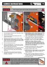
Page 20: ...efore starting check that the chipper is standing level and brush away loose chips SERVICE INSTRUCTIONS 1 Remove side panel 2 Loosen bolt in centre of tensioner pulley with a 19 mm spanner so that pulley is able to slide with minimal wobble 3 Turn nut in end of tensioner pulley slider until correct belt tension is achieved For instructions on checking belt tension correct belt tension values pleas...

Page 21: ...and ensure bolt and washer as note 3 are tightened 9 Refit battery leads 6 3 2 5 4 1 Remove bolt and washer retaining roller box guard and lift guard see diagram on page 18 2 Locate two grease nipples one in the centre of each roller shaft 3 Use a pump action grease gun to apply a generous amount of grease to each roller drive DO NOT USE GRAPHITE BASED GREASE After applying grease to penetrate all...

Page 22: ... of the required maintenance listed in your Environmental Manufacturing LLP instruction manual In the event of a failure the Environmental Manufacturing LLP authorised Timberwolf dealer is to be notified within 10 days of failure and the equipment is to be made available for unmolested inspection by the dealer technician WARRANTY RESTRICTIONS The Environmental Manufacturing LLP warranty is restric...

Page 23: ...G DSSOLHG DSSOLHG DSSOLHG LQFOXGLQJ LQFOXGLQJ LQFOXGLQJ LQFOXGLQJ SDUWV FODXVHV SDUWV FODXVHV SDUWV FODXVHV SDUWV FODXVHV RI RI RI RI 6 6 6 6 1 1 1 1 6DIHW 6DIHW 6DIHW 6DIHW RI RI RI RI 0DFKLQHU 0DFKLQHU 0DFKLQHU 0DFKLQHU DVLF DVLF DVLF DVLF FRQFHSWV FRQFHSWV FRQFHSWV FRQFHSWV 6 6 6 6 1 1 1 1 6DIHW 6DIHW 6DIHW 6DIHW RI RI RI RI 0DFKLQHU 6DIHW 0DFKLQHU 6DIHW 0DFKLQHU 6DIHW 0DFKLQHU 6DIHW GLVWDQFHV ...

Page 24: ...TIMBERWOLF TW 150DHB 23 EXAMPLE IDENTIFICATION PLATE ...

Page 25: ...ning Failure to do so may result in blade s coming loose and damage being caused to the rotor housing Do not pull here When re fitting this guard ensure that steel retaining bracket is on the inside Damaged guards due to incorrect assembly will not be covered by your Timberwolf warranty Decal Description Push to stop Pull to reset Decal Description 616 617 670 1661 1662 4099 2800 2801 2802 2949 30...

Page 26: ...ine without the discharge unit fitted failure to comply may result in serious inury or damage Warning Failure to maintain brake adjustment will result in damper failure No warranty liability will be accepted on this item Danger Autofeed system fitted Rollers may turn without warning When the engine is switched off the rollers will turn during the run down period New drive belts need re tensioning ...

Page 27: ...TIMBERWOLF TW 150DHB 26 ELECTRICAL PARTS LOCATOR Date Last Modified 16th May 06 ...

Page 28: ... TRACER Y R Y BL B R BR O R W BR BR G R P W O W BL O BL G B G BL G P W P W W BL B G BL P W P W B G 35 1mm N O N C N O N C A B MAIN TERM STARTER MOTOR OVER RIDE SP 1 SP 1 SP 1 SP 1 SP 1 SP 1 SP 1 SP 1 SP 1 SP 4 SP 4 SP 4 SP 4 SP 4 SP 2 SP 2 SP 2 SP 5 A B C D C D A B O BL R N O N C 13 14 21 22 N O 13 14 A B C POSITIVE BATTERY CABLE 1375 2 NEGATIVE BATTERY CABLE 1376 2 150 ROAD MACHINE WOULD NOT HAVE...

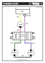
Page 29: ...TIMBERWOLF TW 150DHB 28 HYDRAULIC LAYOUT 0323 MOTOR MOTOR PUMP TANK 3094 17310 4244 1767 4243 FILTER DCV Date Last Modified 31st Aug 05 Hose Kit 4330 ...

Page 30: ... blank page ...

Page 31: ...only be carried out by trained personnel PARTS LISTS Page No BELT TENSIONER 31 CHASSIS 1 32 CHASSIS 2 33 CONTROL BOX 34 CONTROL PANEL 35 DECALS See pages 24 25 DISCHARGE 36 DRIVE TRAIN 37 ELECTRICAL LAYOUT 38 ELECTRICAL PANEL 39 ENGINE 40 ENGINE BAY 41 FUEL TANK 42 FUNNEL 43 HYDRAULICS 44 ROLLER BOX 45 ROTOR 46 ROTOR HOUSING 47 V BELT TENSIONING TABLE 48 ...

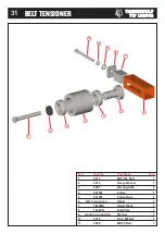
Page 32: ... 1 2 0415 Heavy Washer 1 3 0491 Bearing 6205 2 4 0411M Pulley 1 5 0472M Pulley Boss 1 6 N A to purchase Slider 1 7 0469MS Slider Block 1 8 1342PS End Plate 1 9 made in production Washer 1 10 0476 Plain M8 Nut 1 11 2988 M8 90 Bolt 1 1 2 3 4 3 5 6 7 8 9 10 11 BELT TENSIONER ...

Page 33: ...2 0711 M8 A Washer 4 13 19804FB Lightboard Bracket 1 14 0430 M12 35 Bolt 4 Item Part No Part Name q ty 15 0704 M12 C Washer 24 16 19802FB Beam N S 1 17 19803FB Beam O S 1 18 0314 M12 110 Bolt 4 19 17479 Tow Head 1 20 17509 Brace Plate 1 21 0644 M12 P Nyloc Nut 8 22 3043FS Chassis Handle 2 23 1581 M12 35 Caphead 4 24 17476 Axle 1 25 19663 Wheel inc spare 3 26 1036 M10 Plain Nut 2 27 4010 Brake Rod ...

Page 34: ...19682 Anti Trap Bar O S 1 19 4345 M10 P Nyloc Nut 4 Item Part No Part Name Q ty 20 0052 M10 T Nyloc Nut 4 21 2963 Catch 1 22 0714 M8 Mudguard Washer 4 23 19600 ID Plate 1 24 19683 Anti Trap Bar N S 1 25 0350 M8 25 Bolt 4 26 0712 M8 C Washer 14 27 0701 M10 A Washer 6 28 19681 Rain Flap Clamp 2 29 19691 Rain Flap 2 30 19689 Rain Flap Support 2 31 19664 Mudguard 2 32 19655 Rear Mudguard Bracket O S 1...

Page 35: ...e 2 10 2834 AV Mount 2 11 2804 Bush M10 Top Hat 4 12 2807 AV Mount 20 x 16 2 Item Part No Part Name q ty 13 0857 M5 A Washer 2 14 18103 M5 8 Pan Pozi 2 15 18168 M4 35 Pan Pozi 4 16 1348 Limit Switch 2 17 18100 M4 Washer 6 18 18235 M4 P Nyloc Nut 6 19 made in production 65mm Spacer 1 20 2793FB Bracket Mounting Control Box 1 21 0712 M8 C Washer 2 22 0344 M8 16 Bolt 4 23 0711 M8 A Washer 2 2 1 8 11 9...

Page 36: ... 2 4 1758S Control Panel 1 5 0709 M6 C Washer 4 6 0438 M6 16 Pan Pozi 4 7 0435 M5 16 Pan Pozi 4 Item Part No Part Name q ty 8 1757 Amber LED 1 9 0327 Hours Counter 1 10 Supp d with engine Ignition Switch 1 11 1756 Control Panel Decal 1 12 1397 Throttle Lever 1 13 1470 Rubber Protector 1 1 9 6 x2 x 4 2 4 5 3 8 x 2 12 7 10 0 1 2 11 12 ...

Page 37: ...TIMBERWOLF TW 150DHB 36 DISCHARGE ...

Page 38: ...OLF TW 150DHB 37 DRIVE TRAIN Item Part No Part Name q ty 1 18961M Key 1 2 0410 Taper Lock Bush 2517 1 3 1175 Rotor Pulley 1 Item Part No Part Name q ty 4 0310 Belt SPA 1060 3 5 1170M Engine Pulley 1 1 2 3 4 5 ...

Page 39: ...150DHB 38 ELECTRICAL LAYOUT Item Part No Part Name q ty 1 1975 Funnel Loom 1 2 1406 Safety Bar Loom 1 3 18481 Main Engine Loom 1 Item Part No Part Name q ty 4 1375 VEBattery Cable 1 5 1376 VEBattery Cable 1 1 2 3 4 5 ...

Page 40: ...Electrical Cover 1 7 18107 M6 Wing Nut 2 8 18106 M6 Spring Washer 2 9 0709 M6 C Washer 4 Item Part No Part Name q ty 10 Supp d with loom Relay 1 11 0391 M6 T Nyloc Nut 2 12 4033 M5 AV Mount 4 13 Supp d with loom Fuse 2 14 18291 M5 Plain Nut 4 15 0438 M6 16 Pan Pozi 1 16 1151 Countersunk Pop Rivet 1 17 3024 M5 Spring Washer 4 18 18398 Mounting Bracket 4 16 7 8 4 3 2 1 6 9 x4 x4 x2 12 17 14 11 9 10 ...

Page 41: ...1 19 0708 M5 C Washers 5 20 1090F Throttle Arm Extension 1 Item Part No Part Name q ty 21 0712 M8 C Washer 3 22 0856 M5 20 Pan Pozi 1 23 0807 Fuel Pump 1 24 4315 In Line Fuel Filter 1 25 0699 Throttle Clamp 1 26 1304 Spring 1 27 0435 M5 16 Pan Pozi 2 28 0236 M5 P Nyloc Nut 1 29 2814FS Throttle Cable Clamp 1 30 Supp d with engine Radiator Fan Guard 1 31 0437 M6 16 Bolt 4 32 0709 M6 C Washer 11 33 1...

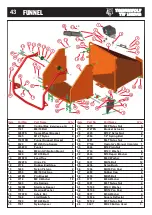
Page 42: ...Nut 3 12 0701 M10 A Washer 2 13 0360 M10 25 Bolt 2 14 0067 Pop Rivet 4 8 x 12 2 Item Part No Part Name q ty 15 4088 Catch Plate 1 16 0235 Catch 1 17 0346 M8 20 Bolt 5 18 0712 M8 C Washer 14 19 0479 M8 P Nyloc Nut 8 20 0704 M12 C Washer 14 21 0318 M12 20 Bolt 2 22 0711 M8 A Washer 2 23 0431 M12 40 Bolt 6 24 0644 M12 P Nyloc Nut 6 25 0348 M8 20 Skt Csk Bolt 4 26 17312FB Side Panel Retainer 1 27 0066...

Page 43: ...TIMBERWOLF TW 150DHB 42 FUEL TANK ...

Page 44: ...Spacer 2 19 1599 Bearing Washer 2 20 1570FR Safety Bar 1 21 1348 Limit Switch 1 22 1520 M10 45 Bolt 2 23 1591 Nylon Spacer 2 Item Part No Part Name q ty 24 0479 M8 P Nyloc Nut 5 25 2727FS Bracket Actuator 1 26 4345 M10 P Nyloc Nut 2 27 2986 1 2 Spring Bolt 2 28 0391 M6 T Nyloc Nut 8 29 P 144 Operator s Manual Cannister 1 30 0046 M12 Plain Nut 4 31 0704 M12 C Washer 8 32 4344 M10 Repair Washer 2 33...

Page 45: ...ptor 1 2 3 4 BSP 1 14 3094 3 8 Hose Bottom Motor to DCV 1 Item Part No Part Name q ty 15 4244 3 8 Hose Hyd Filter to DCV 1 16 1703 Hydraulic Oil Tank 1 17 0225 Adaptor 3 4 3 8 1 18 0152 Washer Dowty 3 4 2 19 1766 Adapter 3 4 3 4 BSP 2 20 0211 3 8 BSP Plug 1 21 1613 Directional Control Valve DCV 1 22 17310 3 8 Hose DCV to Top Motor 1 23 1067 Breather Filter 1 24 1658 M6 12 Bolt 8 25 4219 3 4 Tapere...

Page 46: ...sh Bearing Spline 1 21 0103MH Anvil 1 Item Part No Part Name q ty 22 0228MS Roller Box 1 23 0985 Straight Grease Nipple 1 24 0986 45o Grease Nipple 1 25 0055 Bearing Boss 2 26 0788 Plastic Bush 2 27 1362M Roller Body 2 28 0325M Roller Blade 12 29 0428 M12 30 Csk Soc 24 30 4100M Spline 6B Retro Bottom 1 31 0360 M10 25 Bolt 1 32 0350 M8 25 Bolt 2 33 4068 M10 40 Cap Head Bolt 8 34 0839 M10 C Washer 3...

Page 47: ...CB Bearing Cup 1 7 0796 20 Thou Shim As Req d 8 0701 M10 A Washer 6 9 0900 M10 20 Star Cap Screw 6 Item Part No Part Name q ty 10 083MH Cutter Blade 4 2 11 18275M Blade Pocket 2 12 0386 M10 30 Cap Screw 6 13 1571 Fan Section 2 14 0386 M10 30 Caphead 6 15 18912M Rear Shaft 1 16 4063MCB Bearing Housing Rear 1 17 0495 Bearing 6208 1 1 2 3 9 10 11 12 5 6 4 13 15 16 14 13 17 9 10 12 11 14 7 8 ...

Page 48: ...Pozi Pan 4 3 0709 M6 C Washer 4 4 1758S Control Panel 1 5 1267FO Front Plate 1 6 0702 M12 A Washer 15 Item Part No Part Name q ty 7 0045 M12 T Nyloc Nut 15 8 0355 M8 16 C Sunk Bolt 2 9 1268FO Access Cover 1 10 18023PS Guard Stand Off Plate 1 11 0101MH Anvil Vertical 1 5 1 2 3 4 6 7 8 9 7 6 11 x13 x2 x4 10 ...

Page 49: ...UHDGLQJ UHDGLQJ JI JI JI JI 1HZ 1HZ 1HZ 1HZ EHOW EHOW EHOW EHOW 8VHG EHOW K METHOD 1 SET THE DEFLECTION DISTANCE ON THE LOWER SCALE OF THE TENSION GAUGE SO THAT THE UNDERSIDE OF THE O RING EqUALS THE h VALUE GIVEN IN THE TABLE BELOW 2 ENSURE THAT THE DEFLECTION FORCE SCALE IS ZERO D BY PUSHING THE UPPER O RING ALL THE WAY DOWN 3 PLACE THE TENSION GAUGE IN THE CENTRE OF THE BELT SPAN AS SHOWN IN TH...

Reviews: