Only use bicarbonate of soda (baking soda) only as blasting media. Use with other blasting media may cause
damage to the machine.
Use only clean, dry, regulated, compressed air as power source. DO NOT use oxygen, carbon dioxide or any
other bottled gas as air source.
Do not exceed 100PSI during operating this soda blaster.
Check for any broken parts and sealing security before operation.
Turn OFF the valve (7) and discharge any remaining air pressure after each use or before adjusting the blaster.
Keep the work piece stable and firmly secured to prevent movement when using this blaster. It is strongly
recommended testing the blaster in small media flow rate before starting the work so as to avoid injury to
persons.
Any repairs or parts replacements should be made by qualified technicians. Use the authentic parts for
replacement only.
WARNING: This product, when used for abrasive blasting and similar applications, produces chemicals known to the
State of California to cause cancer and birth defects (or other reproductive harm). (California Health & Safety Code §
25249.5, et seq.)
WARNING: The brass components of this product contain lead, a chemical know to the Stage of California to cause
birth defects (or other reproductive harm). (California Health & Safety Code § 25249.5, et seq.)
Specifications
Air pressure range: 35-90 PSI
Maximum Air pressure: 100 PSI
Air Inlet 1/4” -18 NPT
Media Capacity: 40 lbs
Media Type: Sodium Bicarbonate (Baking Soda)
Assembly and Operation Instruction
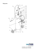
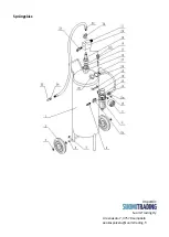
Assembly:Carefully remove the tool from the package and following the steps to install refer to the assembly
diagram.
1.
Insert the wheel shaft (4) through the holes on the back legs of the storage tank (1). Place a washer (3) on both
side of the wheel (2) and place onto the wheel shaft (4),securing with the cotter pin (5). Repeat for the opposite
side wheel.
2.
Wrap the threads of the quick disconnect fitting (11) with thread sealer tape and screw it into the media regulator
(20).
3.
Wrap the threads of the safety valve (23) with thread sealer tape and screw it into the media regulator (20).
4.
Wrap the on off valve (7b) with thread sealer tape and screw it into the media regulator (20).
5.
Screw the pickup tube (18) into the media regulator (20).
6.Wrap the thread of the bushing (19) with thread sealer tape and screw it into the media regulator (20).
7.Insert the pickup tube (18) through the o-ring (17), bushing (19), and then into the storage tank (1). Screw tightly
the hex nut (16) in the storage tank (1).
8.Unpacking the regulator (8), wrap the threads of the pressure gauge (9) and assemble the regulator (8) and
pressure gauge (9). Install the bracket (14) below the compression nut (13).
9.Attach the regulator (8) to the storage tank (1) by securing the bracket (14) and tank bracket (15) using the socket
head cap screws (10).
10. Wrap the threads of the air input on off valve (7a) and screw it into the left side of the regulator (8).
11.Wrap the threads of the male coupler (6) and screw it into the air input on off valve (7a).
12.Wrap the threads of the quick disconnect fitting (11) and screw it into the right side of the regulator (8).
13.The air hose (12) should be attached to the quick disconnect fitting (11) in both ends.

