background image

1017 Technical Manual 

3. 

Operation 

3.1.  Preparing for Use 

Before using the 1017, you must first check to see if the battery level indicator shows that 
the batteries are in a good state of charge.  If the indicator shows that they are low then you 
must recharge them by plugging the 1017 into the mains supply. It will take approximately 
12 – 14 hours to fully recharge the battery pack. You may of course use the 1017 when it is 
plugged into the mains supply irrespective of the battery state. The batteries should also be 
checked during operation. 
  

3.2.  Using the 1017 

Firstly, select the correct range on the range select switch ensuring that the output polarity 
switch is ’OFF’ and that nothing is dialled up on the digit switch.  Then dial up the required 
value on the digit switch. The output may then be supplied to the unit under test by selecting 
the output polarity switch. 
  

Note:

 When the output switch is set to the ’OFF’ position, there is a short circuit on the 

output terminals. 
  
Caution must be exercised when using the 100V range against possible electrical shock. 
  

3.3.  Thermal EMF's 

When using the 1017 to provide a precision voltage of less than 1mV, care must be taken to 
avoid Thermal EMF’s. These occur where temperature differences are present at the 
junctions of dissimilar metals, e.g. – A normal solder to copper junction has a thermal EMF 
of approximately 3uV/°C. Errors in the 1017 under stable temperature conditions are 
typically less than +/- 0.2uV/°C. 
  

3.4.  Using the Deviation Control 

Note:

 The digital deviation control has no effect if used on the resistance range. 

  
To apply a percentage deviation to the output, select either positive or negative deviation 
with the control switch and dial up the percentage deviation required on the digit switch. 
  
Alternatively, if the output is set to the correct value and the reading on the U.U.T. reading 
differs from this, adjust the deviation control to give the required value. The error can then 
be read directly, as a percentage, from the deviation control. 


Summary of Contents for 1017

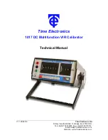
Page 1: ... Ltd Botany Industrial Estate Tonbridge Kent TN9 1RH Tel 44 0 1732 355993 Fax 44 0 1732 770312 Email mail TimeElectronics co uk Web Site www TimeElectronics com Time Electronics 1017 DC Multifunction VIR Calibrator Technical Manual ...

Page 2: ...3 2 Using the 1017 7 3 3 Thermal EMF s 7 3 4 Using the Deviation Control 7 4 Calibration 8 4 1 Calibrating the 1017 8 4 2 Zero Adjustment 8 4 3 Calibrating the Full Scales 9 4 4 Calibrating the Deviation Control 9 5 Guarantee S ervicing 10 All Time Electronics instruments are subject to continuous development and improvement and in consequence may incorporate minor detail changes from the informat...

Page 3: ...y The 1017 s basic reference source is a specially aged computer selected precision reference diode The diode provides the input to the instruments active circuitry which incorporates several high performance chopper stabilised amplifiers with a zero stability of less than 0 5uV per C and a warm up time of less than 1 minute The precision resistors used in the 1017 are high performance types with ...

Page 4: ...put resistance All specification 3uV Current Range 0 99 9999mA in 100nA steps Accuracy 100mA range 0 02 of setting and 0 004 of range Drive Voltage 10V Maximum Resistance Range 0 9 99999kΩ in 10mΩ steps Accuracy 0 05 of full scale Power Rating 250mW per Resistor End Resistance 200mΩ Deviation Control Only on Voltage and Current Range 0 001 to 0 999 in 0 001 steps Accuracy 0 5 Accuracy Stability Le...

Page 5: ...complete amplifier regulates the output to the set output value When the 100mA range is selected the output current is sensed by a precision resistor The voltage generated across this resistor is used to control the output drive voltage so regulating the output current The resistance range operates by directly switching the thumbwheel switch to the output terminals The deviation control operates b...

Page 6: ...Battery Level Indicator 5 Range Select Switch Selects the output maximum output 6 Range Output Digit Switch Selects the value of output 7 Deviation Digit Switch Selects the value of Deviation 8 Battery Level Indicator Shows the state of charge of the batteries 9 Positive Off Negative Deviation Control Applies a Positive or Negative Deviation to the output as a percentage 1 2 3 4 5 6 7 8 9 ...

Page 7: ...tch is set to the OFF position there is a short circuit on the output terminals Caution must be exercised when using the 100V range against possible electrical shock 3 3 Thermal EMF s When using the 1017 to provide a precision voltage of less than 1mV care must be taken to avoid Thermal EMF s These occur where temperature differences are present at the junctions of dissimilar metals e g A normal s...

Page 8: ... resistance ranges with a specification of at least 4 times greater than that of the 1017 s specifications Calibration is best carried out on fully charged batteries without the mains supply connected to ensure that no mains supply interference takes any effect on the readings 4 2 Zero Adjustment Range Allowance Adjust Pot 1V 6µV 1V ZERO ON MODULE ...

Page 9: ... read 100mV to within 4 3µV Done on 100mV Range Check 10mV F S is within 1 3µV Adjust the 100V F S trimmer VR6 to read 100V to within 3 5mV Adjust the 100mA F S trimmer VR7 to read 100mA to within 6uA 4 4 Calibrating the Deviation Control Set the output to the 1V on the 1V range and set the deviation to 0 999 Adjust the output using the Deviation trimmer VR9 to read 1 01V to within 5mV Leaving the...

Page 10: ...ecialised knowledge needed to keep your instrument in peak condition and we also maintain a comprehensive spare parts service Please enclose details of the service required and your full company details including a contact name when returning for servicing Returning Instruments When returning instruments please ensure that they have been adequately packed preferably in the original packing supplie...

Reviews: