background image

10 

1021 Technical Manual 

10 

6. 

Maintenance and R epair 

6.1.  Maintenance 

 
Dismantling the Instrument 

Remove rubber protection boot and then removal of four 2.0mm CSK screws enables the 
blue cover to be taken off which provides access to all parts of the instrument. 
  
The range switch assembly can be removed by disconnecting the 9-pin connector and 
removing the two front panel locating screws. 


Fuse Replacement


The power supply and output fuses are mounted on the power supply printed circuit board 
and are easily accessible on removing the instrument cover.  Fuses are rated at F1A (F1), 
and F250mA (F2), and have dimensions 20mm length by 5mm diameter.  The fuses are 
available from Time Electronics Ltd or your local supplier.  


6.2.  Repair 

 
NOTE:  No repair work should be undertaken by the customer while the instrument is 
under warranty as such work may render the warranty invalid. 
 

Some of the precision components used in this instrument are not readily available and 
make repairs by the customer difficult if these components are damaged. 
  
Overload conditions can cause a fuse failure which will be indicated by one of the following 
conditions: 
  
a)   Instrument inoperative and battery level indicator at zero. 
      Possible cause –F1, F1A supply fuse blown. 
  
b)   Battery level indicator displaying but no output at the output terminals.     
      Possible cause – F2, F250mA output fuse blown. 


Fuse Location

M

O

DUL

E

F2  F250mA

J2

BATTERY PACK

BATTERY PACK

F1  F1A

Summary of Contents for 1021

Page 1: ...otany Industrial Estate Tonbridge Kent TN9 1RH Tel 44 0 1732 355993 Fax 44 0 1732 770312 Email mail TimeElectronics co uk Web Site www TimeElectronics com Time Electronics 1021 Current Source With Null Measuring Facility Technical Manual ...

Page 2: ...echarging 7 4 E lectrical Nois e Pick Up 8 5 Circuit Des cription 9 5 1 Power Supply 9 5 2 Mains Recharger 9 5 3 Circuit Module and Range Switch 9 6 Maintenance and R epair 10 6 1 Maintenance 10 6 2 Repair 10 7 R ecalibration 11 7 1 Calibration Procedure 12 7 2 Linearity 13 8 Guarantee S ervicing 14 All Time Electronics instruments are subject to continuous development and improvement and in conse...

Page 3: ...en used even if a contact fails the 1021 will still operate correctly The accuracy and stability are such that a wide range of applications are possible In the process industries it may be used to test and calibrate current sensitive transducers and their associated indicating and recording instruments The semiconductor industry requires constant current sources for parameter measurements It may a...

Page 4: ...m per ºC 10 ºC to 50 ºC Better than 25 ppm per hr at constant temperature Null Sensitivity Adjustable from 25mA to 25uA Load Regulation Better than 20 ppm per volt change in output Power Supply 8 NiMH rechargeable batteries with external mains re charger Standard mains voltage is 220 250V 50 60Hz 100 125V 50 60Hz is available but must be specified on order Dimensions 200 x 75 x 110mm 215 x 100 x 1...

Page 5: ...5 1021 Technical Manual 5 2 Controls 1 8 9 7 3 5 2 6 4 10 11 12 ...

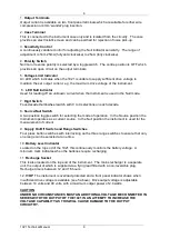
Page 6: ...n each decade 8 Source Null Switch A two position toggle switch for selecting the mode of operation In the Source position the instrument operates as a current source In the Null position the instrument is used for the measurement of current 9 Supply On Off Switch and Range Switches Four press button switches with interlocking on the three range switches to ensure that only one range can be select...

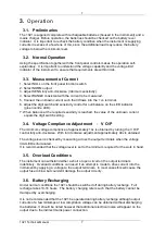
Page 7: ...the unknown current equals the digit switch setting 3 4 Voltage Compliance Adjustment V O P The minimum voltage compliance of approximately 14v is obtained by turning the V O P control fully anti clockwise With full clockwise adjustment approximately 40v is obtained The voltage level is checked by measuring across the output terminals when the voltage limit LED is illuminated It is recommended tha...

Page 8: ... terminals of the 1021 the voltage noise measurements must be divided by the load resistance to give the current noise A certain amount of noise is generated internally by the 1021 and when high load resistances are used this can be seen on the output terminals as a series of voltage spikes The effect of this voltage noise on the output current is very small and does not affect the DC accuracy Two...

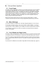
Page 9: ...ife of a fully charged battery should be up to 20 hours 5 2 Mains Recharger The mains recharger is a separate unit It will fully charge the batteries in 12 to 16 hours The standard recharger requires a mains input of 200V to 240V at 50 60Hz A recharger requiring 100V to 120V at 50 60Hz is also available but should be specified when ordering The recharger is connected to the 1021 by a miniature 2 p...

Page 10: ...ensions 20mm length by 5mm diameter The fuses are available from Time Electronics Ltd or your local supplier 6 2 Repair NOTE No repair work should be undertaken by the customer while the instrument is under warranty as such work may render the warranty invalid Some of the precision components used in this instrument are not readily available and make repairs by the customer difficult if these comp...

Page 11: ... available before attempting recalibration There are 2 ways the 1021 can be recalibrated a The output current can be converted to a voltage by connecting a precision resistor across the output terminals 3 values are required 100 1K and 10K ohms The resistors must be accurate to better than 0 01 and have a good stability under load The 10 ohm will dissipate 0 1 watts at 100mA and therefore must hav...

Page 12: ...ll digits to zero adjust the ZERO trimmer to give 1 micro amp output For recalibration method a the precision 1K ohm resistor should be connected to the output terminals Note the zero adjustment is unipolar i e it is not possible to adjust the output to less than zero 2 Select the 1mA range and set all digits to 9999 Adjust the 1MACAL trimmer to bring the output to exactly 1mA For recalibration me...

Page 13: ...ng conditions the high performance of these resistors ensures that the 1021 linearity will remain within specification for the instrument s lifetime Should the resistors be damaged or become faulty a replacement procedure should be adopted ensuring that the replacement resistor s is matched to the others on that digit bank The 1K ohm values should be matched to 0 01 the 100 ohms to 0 05 the 10 ohm...

Page 14: ...pecialised knowledge needed to keep your instrument in peak condition and we also maintain a comprehensive spare parts service Please enclose details of the service required and your full company details including a contact name when returning for servicing Returning Instruments When returning instruments please ensure that they have been adequately packed preferably in the original packing suppli...

Reviews: