background image

INST

ALLA

TION  & OPERA

TING INSTRUCTIONS

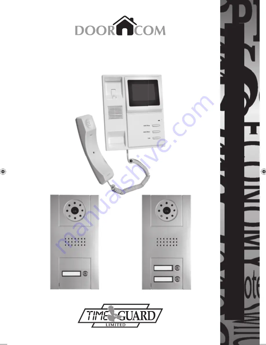
DOOR VIDEO COMMUNICATOR

Model: DCC3 Single Channel Black & White

DCC4 Twin Channel Black & White

DCC3/4

DCC4

DCC3

DCC3_DCC4_Instructs_1.3.indd   1

DCC3_DCC4_Instructs_1.3.indd   1

30/1/07   11:05:24 am

30/1/07   11:05:24 am

Summary of Contents for DCC3

Page 1: ...INSTALLATION OPERATING INSTRUCTIONS DOOR VIDEO COMMUNICATOR Model DCC3 Single Channel Black White DCC4 Twin Channel Black White DCC3 4 DCC4 DCC3...

Page 2: ...between these units is limited to 15m By using 13 0 2 bell flex cable this distance can be increased to a maximum of 70m 2 Product Overview If operation with an electric door catch is required then p...

Page 3: ...2 RED BROWN RED BROWN RED BROWN RED 6 7 6 7 BROWN Fig 2 Wiring diagram DCC4 shown External intercom Door catch Internal intercom 2 not for DCC3 Internal intercom 1...

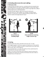
Page 4: ...le to potential entrants It should be mounted at the height indicated in fig 3b Fig 3a Internal intercom mounting height Fig 3b External intercom mounting height and coverage 3 2 Cabling Connection be...

Page 5: ...e terminals of the same colour on the external intercom particularly important if an extension cable is used If a DCC4 is being installed then a second cable will be required to connect to the additio...

Page 6: ...ig 2 Arrange this cable and the mains lead in the cable channel at the back of the internal intercom Finally locate the internal intercom mounting slots on the wall fixing plate mounting hooks and sli...

Page 7: ...ase of damage to the product unplug the mains plug from the 13A socket to avoid any possibility of electric shock and have the damage examined by a competent person 3 When laying cabling ensure that n...

Page 8: ...event of this product becoming faulty due to defective material or manufacture within 3 years of the date of purchase please return it to your supplier in the first year with proof of purchase and it...

Reviews: