background image

20 


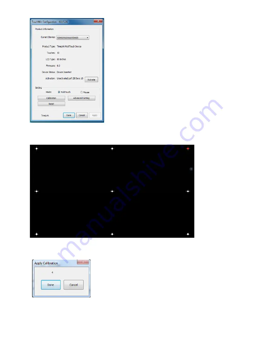
Click


to


calibrate,


enter


the


nine

point


calibration


interface,


start


from


the


red


calibration


point


sequentially


from


the


upper


left


corner


of


the


start,


put


the


touch


pen


vertically


in


the


middle


of


the


red


dot


cross,


after


each


click


the


red


dot


will


move


backward


in


turn,


the


following


picture


shows


the


calibration


point


of


the


third


points:


Complete


the


9


calibration


points


one


by


one,


there


will


be


countdown


to


prompt


successfully


calibrated,


you


can


also


manually


click


the


"Done"


key


,


indicating


the


completion


of


correction,


as


shown


below:


2.7


Restart/Shutdown


In


some


circumstances


the


system


need


to


be


restarted,


when


the


system


panel


is


at


the


unlocking


state,


you


can


press


Summary of Contents for TL6510-II Series

Page 1: ...All in one Multimedia Whiteboard Teaching Machine TL6510 II Series Product Operation Instructions Shenzhen TimeLink Technology Co Ltd ...

Page 2: ...ction of central control panel 14 1 1 Diagram of central control panel 14 1 2 Access Control 14 1 3 System Control 14 1 4 Display 15 1 5 Volume Control 15 1 6 USB Extension 15 1 7 External connection 15 2 Basic Operation 16 2 1 Unlock the Access Control 16 2 2 IC Card Administration 17 2 3 Password Administration 18 2 4 Restore Factory Settings 19 2 5 Boot 19 2 6 Touch Screen Calibration 19 2 7 Re...

Page 3: ...4 1 Notes 28 2 Configure serial code tools 28 ...

Page 4: ...device Please keep the device away from heat source Please do not use the device in a humid environment Avoid the possible electric shock Please do not connect or disconnect any cable or repair or re configure during lightning storm Do not use the device during lightning storm Do not stuff matters into the vent or the opening hole of the device otherwise it may lead to fire or electric shock due t...

Page 5: ... antenna Increase the separation between the equipment and receiver Connect the equipment into an outlet on a circuit different from that to which the receiver is connected Consult the dealer or an experienced radio TV technician for help This device complies with Part 15 of FCC Rules Operation is subject to the following two conditions 1 This device may not cau se harmful interference and 2 This ...

Page 6: ...e demonstrations such as writing annotating operating information processing unit courseware demonstrating computer aided drafting text entering handwriting recognizing saving or annotating the pictures or videos collected by high speed scanner audio or video playing etc The control unit performs a centralized control of the projector switch sound box switch information processing unit switch etc ...

Page 7: ...rol system only by software configuration Sound box 2 20W full frequency audio Central control system including access control system control projector control volume control USB2 0 interface extension and external connection of VGA and USB Object booth projecting objects items homework test paper etc to the whiteboard and annotating on the object is available Electronic whiteboard multi touch ant...

Page 8: ...arallel scale Ensure two buckles parallel Spanner Screwing the setscrew Pencil Drawing auxiliary line for hole location 1 2 Operation steps 1 2 1 Calculating the height of the holes Determine the whiteboard center and then according to the position of the center calculate the heights of two lines of holes The calculation method is as follows Distance C from board projection center to hole in the u...

Page 9: ... in the previous step with parallel scale 1 2 3 Marking position of the buckle Determine the central position of the buckles respectively according to the marks in the drilling size diagram Intersection of marked horizontal lines Distance C from board projection center to hole in the upper row Distance B from board projection center to hole in the lower row Intersection of marked horizontal lines ...

Page 10: ...o the hole position marked in the previous step 1 2 6 Hanging on the wall Lift the board and hang it on the buckle with left side and right side aligned At same time the height of hook should be a little higher than the buckle The following figure shows the back side Drilling depth of 6 drill of percussion drill 80mm Horizontal distance D from buckle center to board center Horizontal distance D fr...

Page 11: ...tion of projector 0 5m projecting 80 Please consult the projector manufacturer according to your projector to obtain the installation method and cautions 3 Installation and maintenance of OPS The OP center of the device adopts an OPS computer When you receive our device the OPS computer has been already installed at the back of the device OPS computer ...

Page 12: ... 1 Installation and disassembly of OPS When disassembling the OPS pull out the connected cable screw two screws which is used to fix the OPS to the frame hangers and then pull it out along the chute The OPS can be installed conversely ...

Page 13: ...according to the record card after boot steps to register for the entrance card There are warning tone and indicator lamp in each time of using card and entering password If it is unlocked successfully the buzzer rings and RFID indicator lamp turns on if it fails the buzzer only makes di di sound for twice The panel will get locked in the following situations 1 shortly after electrified 2 pushing ...

Page 14: ...he centralized control but by hand What it should be highlighted is that through the internal USB sound card there is no need for host audio output wire or external audio enter wire but one USB wire is enough which means it is by USB wire that the host volume and external volume are transferred into the centralized control Using B type USB enter port for external connection saves external audio wi...

Page 15: ... in any non administration mode you can enter the administration mode by enter the administrator password and then press the key to confirm Exit administration mode press the 0 key and hold it for 3 seconds you will exit from the administration model after hearing the prompt tone like Di If there is not any operation on the numbering keys under the administration mode for 5 seconds it will automat...

Page 16: ...ny other voice or no voice then this is invalid To record a card you have to swipe it for three times and this card is recorded as effective card after the buzzer makes a long blast of sound This operation can be carried out continuously To record the card continuously In the process of recording the card if you heard any Di Di warning sound then you failed in recording the card you need to press ...

Page 17: ...mbers as password again and then press key to confirm enter the numbers of administrati on password then press key press and hold key for 3 seconds Enter 6 numbers as passwor d then press key to confirm A long blaster of sound The password is successfull y registered Y N Administrator password modification Enter the administration mode press and hold the 1 key for 3 seconds when hear a Di please e...

Page 18: ...nes are correctly connected in accordance with the installation requirements the control system will be initialized immediately and the function keys will be locked after the central control panel is power on in this time you need to enter the administrator password 888888 and confirm by pressing the key when you heard a long Di it is unlocked press the boot key at the system control area when exe...

Page 19: ... red dot will move backward in turn the following picture shows the calibration point of the third points Complete the 9 calibration points one by one there will be countdown to prompt successfully calibrated you can also manually click the Done key indicating the completion of correction as shown below 2 7 Restart Shutdown In some circumstances the system need to be restarted when the system pane...

Page 20: ...g signal box will pop up Click to start recording and then you can see the green signal on the right will change with the audio frequency and blinking At the same time the recording time is displayed The size of the recording files is almost not limited by the recording time and is stored in the host hard disk When simultaneously open multiple audio files will be recorded in audio synthesis form t...

Page 21: ...in the central control panel and press you can find the light in the lock key turns on Before Unlocked After Unlocked 3 When do not use the video booth you can lock it by pressing the lock key in the central control panel 2 2 Turn On Off the Video Booth 1 after the unlock indicator to gently hold the first panel push the unlocked second finally the pop up on instrument panel with handle gently hol...

Page 22: ...ner arm and then close the both sides of the plate and then rotate upward to close 3 Operation Instructions for High speed Scanner Software To use a video booth first is to ensure the driving and lecture software are well installed before open lecture software Then you can use the high speed scanner normally You should pay our attention to that if been connected to the external USB the high speed ...

Page 23: ...nter full screen marking and the software will generate a new icon at the bottom and the screen will enter the marking state you can un limit dialog operation through the Unmark icon you can also mark in full screen Bottom icons Reflect the shooting screen with true color for example Reflect the shooting screen with the background for example Reflect the shooting screen with in gray form for examp...

Page 24: ...he characteristics of JF 303A Equipped with four functions i e the wireless microphone PPT turn page the laser pointer and remote controller the computer music player built in microphone and set the external microphone interface can be matched with a head mounted MIC The built in lithium battery and charging module are equipped with a low voltage alarm charging indicator automatic shutdown after c...

Page 25: ...y switch to the notebook but the projector projection screen need to manually switch to external 4 When using foreign notebook the information of projection is incomplete It is related to the notebook graphics driver suggest to update to the latest official version 5 Find the volumes of recording and the source file are different Click on the volume icon at the lower right corner click the right m...

Page 26: ...rrent 12 5mA IC registration number 256 pcs swiping distance 3cm Numbering password contains the default password the password can be registered and deleted 6 numbers Power amplifier 2 20W 112dB Multi function USB Whether it is for connection to a host or external laptop a USB port has implemented to read and write audio and USB and external USB has automatic switching function Record Realize the ...

Page 27: ...tool 2 Among which the VGA2 serial code should be filled with the video serial code provided in the specification of the projector 2 Configure serial code tools 1 Open the projector exe software as shown below 2 If there is a projector serial configuration file click Open key select the serial port profile of the projector such as YaTu r0 scheme as shown below If there is no projector serial confi...

Page 28: ... into the central control panel below is the symbol of successful written click Read button to view the written serial code value After completing the steps above the central control panel can normally control the corresponding functions of the projector ...

Reviews: