background image

Summary of Contents for C-POWER 250

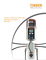
Page 1: ...Timken C Power Lubricator Operating System Manual...

Page 2: ......

Page 3: ...12 5 1 Display Elements 5 2 Function Indication on the Display 5 3 Function Indication via the LED Signal Lights 5 4 Control Buttons 6 Operation and Control 13 6 1 Preparations 6 2 Questions to Ask Pr...

Page 4: ...me and improve safety 1 1 Delivery Content Timken C Power will be delivered according to customer specifications for type of grease and size of the C Power LV unit The user will only need to assemble...

Page 5: ...ing addition and or variation is considered inappropriate 1 5 Legal Requirements Liability The information data and tips contained in this operating manual were current as of the printing date No clai...

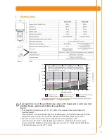
Page 6: ...efore any changes are made Only original tube connections and connectors from Timken can be used on or with the lubrication system These will withstand high pressure up to 360 psi 25 bar Ambient media...

Page 7: ...rease Correct Answer 3 m maximum tube length for standard grease 5 m maximum tube length for low temperature grease arrow 1 meets the dashed line of the standard grease range at 3 m 2 You want to use...

Page 8: ...ower LV unit which can be supplied in 250 cc and 500 cc versions Lubricant can be requested by the customer Use only Timken C Power LV units Battery set consisting of two batteries The batteries are n...

Page 9: ...t the lubrication points and the complete lubricant tube are pre lubricated with the same lubricant that is contained in the C Power LV unit To do this Timken offers a 400 g lubrication cartridge for...

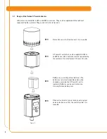
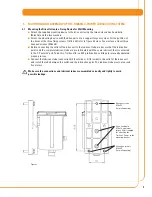
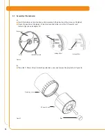
Page 10: ...position of the jumper It must correspond to the size of the C Power LV unit refer to figure 4 and chapter 7 1 Figure 4 b Place the C Power LV unit inside the protection cover and remove the plug refe...

Page 11: ...r to figure 6 Figure 6 d Place the C Power LV unit with its protection cover on the drive unit Make sure that the catch locks in place and that the teeth of the C Power LV unit and the drive unit inte...

Page 12: ...figure 8 chapter 5 1 The display shows settings operating conditions and error messages When no errors are present the display shows the remaining volume of the mounted C Power LV unit in percent volu...

Page 13: ...ounting device should be used when installing the Timken C Power The lubricant tube must be installed and mounted correctly The length of the lubricant tube should not exceed five meters The tube must...

Page 14: ...onnections Regularly check the filling level of the transparent C Power LV unit After several additional discharges calculate the reduced discharge period and note it on the lubrication and maintenanc...

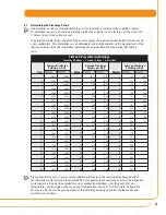
Page 15: ...ion of the remaining discharge period in the lubrication and maintenance schedule 15 Days Average Discharge Volume per Day Weeks Average Discharge Volume per Day Months Average Discharge Volume per Da...

Page 16: ...h from days to weeks to months within the setting mode by pressing the MODE SAVE button Figure 16 The figures on the display are blinking and the setting mode is shown If you have reached the desired...

Page 17: ...eviously set mode ON or OFF without saving the changes The original settings remain valid Additional Discharge With an additional discharge a lubrication point can be supplied with an additional amoun...

Page 18: ...ional discharges with every regular discharge 6 9 Calculation of the Remaining Discharge Period Please note that in case of one or several additional discharges the remaining discharge period of the l...

Page 19: ...e of the C Power LV Unit Set the size of the C Power LV unit by inserting the contact pin jumper into the base plate of the battery compartment in the drive unit refer to figure 22 Pointed pliers can...

Page 20: ...and the drive unit interlock The control system will automatically recognize the new C Power LV unit The display will indicate if the Timken C Power was switched off prior to the replacement of the C...

Page 21: ...Timken C Power distribution block E2 Lubrication system has been shut off Drive mechanism of the distributor is defective Check the coding pins and carry out an initialization E3 Lubrication system ha...

Page 22: ...low local waste disposal regulations 10 SERVICE Please contact your local Timken distributor for availability and cost of the following Returning an empty lubricator for environmentally safe recycling...

Page 23: ...cs Connector Where the connecting cable plugs in Connecting piece 6 pcs Used to attach the lubricant tubes Plug 4 pcs Seals outlets that are not used Bores 1 to 6 Where the coding pins are inserted in...

Page 24: ...des of the lubricator and the distributor are level Attach distributor and lubricator to the mounting device using the four bores Connect lubricant tubes to connecting pieces Position them between the...

Page 25: ...operating condition Connector for distribution block Connection thread G 3 8 outside and G 1 8 inside for application into a lubrication point or for connecting a grease tube DISPLAY Configuration men...

Page 26: ...eeth of C Power LV unit and drive unit interlock Turn the cover clockwise until the bayonet catch locks in place 2 Starting the C Power Hold down the ON OFF SELECT button until Remaining Volume appear...

Page 27: ......

Page 28: ...www timken com Timken is the registered trademark of The Timken Company 2006 The Timken Company Printed in USA Order No 999 10793...

Reviews: