More detailed description of the turnstile operation modes is given in section 1.8 "Description
and operation of controller as a component of the turnstile”.
1.4.3.4
The turnstile 12V DC power voltage is provided by power supply unit.
1.4.3.5
The turnstile wiring diagram is shown in Annex C.
1.5
Instrumentation, tools and accessories
Dedicated tools are not required for installation of the turnstile (multi-purpose
measurement instrumentation and installation tools are sufficient
(See Fig. 8)
).
Fig. 8 -
Tools and accessories for installation
puncher
;
concrete drills
(
according to diameter of anchors included in the turnstile scope of delivery);
extension cord
;
kit of end and pin wrenches
;
kit of hexagons
;
kit of screwdrivers
;
hammer
;
multimeter (tester)
;
measuring tape
marker
;
pliers, side cutters
;
builder's level
.
13
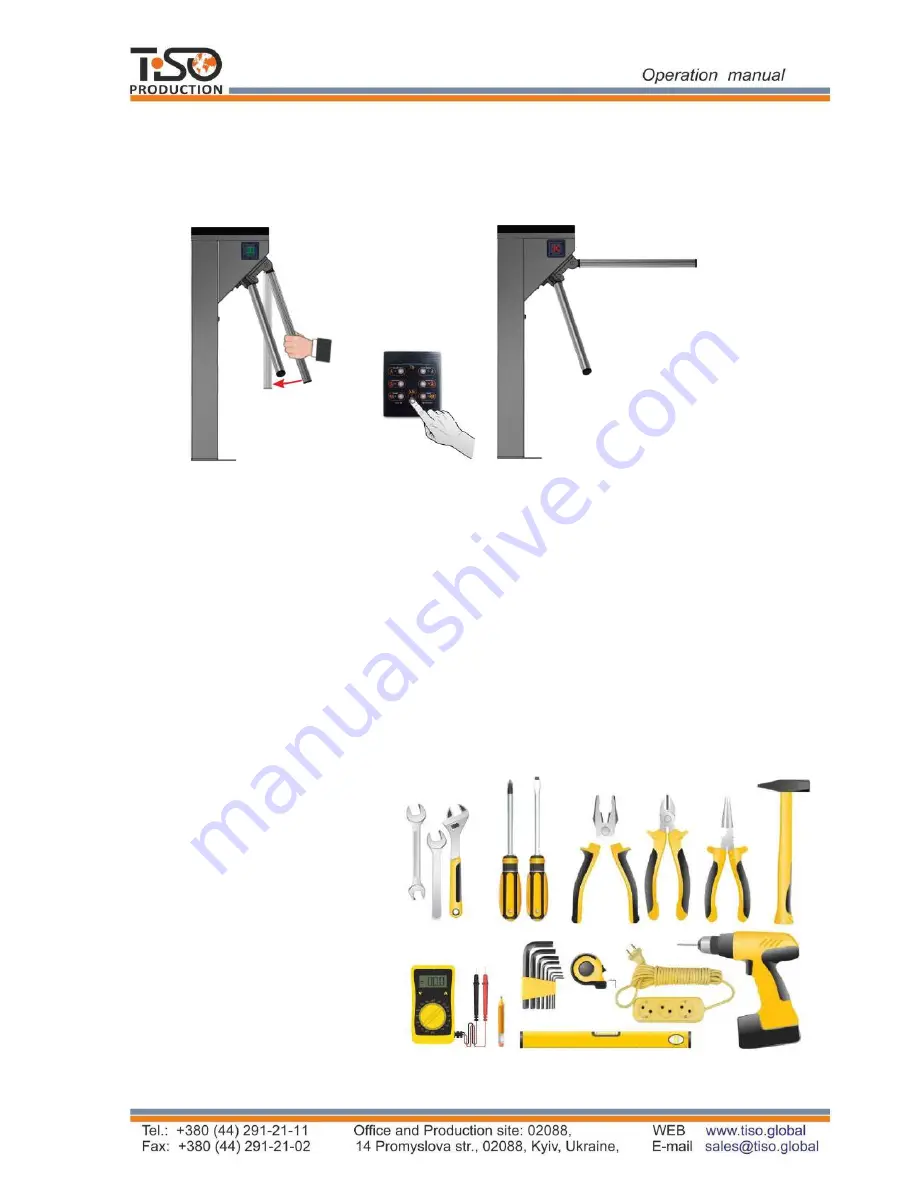
After the signal is deactivated from the input (
in1
) or deactivation of the panic mode from control
panel, a barrier rod is automatically re
set
to its initial position.
Before turning on the power and turning off the panic, you need to manually check the verticality of
the barrier rod (if necessary, lower the leash manually to the stop). After full recovery - check the
blocking of all three barrier rods.
Fig.7 - Deactivation of the "PA
NICA" mode and restoration of the leash to the starting position
b) The positions of the restored rod
in the
"Standby"mode
"PANIC" mode before restoring
a) The positions of the rod in the


