31
10)
WARNING
:
Cables to be pulled in corrugated or metal pipes;
The length of cable free ends to be at least 1 m to provide their entry,
termination and connection to the relevant terminals in the turnstile rack.
The cable outlet point to be aligned with the hole on the turnstile mounting
plate
(Fig.1
5
-1
7
)
.
11) The following cables to be pulled to the turstile installation site:
Power supply cable 230 V ~;
Control panel link cable;
Access control system (ACS), if any, connection cables;
12) The turnstile to be installed upright at the
prepared location.
-
Cables to be pulled through available
service hole in the turnstile rack bottom
butt end part by reclining the turnstile
(Fig.12).
-
Fixation holes at the turnstile bottom
plate to be aligned with prepared surface
holes.
13) Turnstile connection
(Fig. 1
8
):
а) Power supply cable ~230 V to be connected
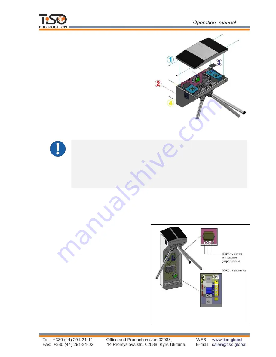
The lid to be removed by unscrewing 4 screws
on butt ends (
Fig. 15
) to access to the
"
SKULL-M
" tripod turnstile fixation and
service holes as well as terminal blocks
(See
Fig.17).
Fig. 17
– General view of the "SKULL-M"
tripod turnstile assembly
Control panel link cable
Power supply
cable
Fig.
1
8
–
Connection of power supply and
control panel link cable
-
Phase L to be connected to circuit breaker
;
-
N
e
ut
ra
l
(N)
to
be
conn
e
ct
e
d
to
t
er
min
a
l
~230V;
-
E
ar
th
(РЕ)
to
be
conn
e
ct
e
d
to
ear
thing
t
er
min
a
l
(РЕ).


