17
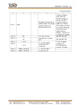
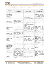
Table 5
№
Connec
tor/cont
act
Description
Directio
n
Designation
Signal description and
parameters
1
2
3
4
5
ХТ4/1
INP1
(«TO BE OPENED
A»)
ENTRY
Command "TO BE
OPENED FOR SINGLE
/ FREE
ACCESS"
1) logical «0» (0
2,2)
V;
2) logical «1» (3
5)
V;
3) active level of
signal (factory setting)
logical «0»
4) voltage on open
input < 5 V
ХТ4/2
INP2
(«TO BE OPENED
B»)
ENTRY
ХТ4/3
INP3
(«PANIC»)
ENTRY
Command "SWITCHING
TO PANIC STATE"
ХТ4/4
INP4
ENTRY
Not applicable
ХТ4/5
INP5
ENTRY
ХТ4/6
INP6
ENTRY
ХТ4/7
GND
COMMON WIRE
ХТ3/1
GND
COMMON WIRE
ХТ3/2
OUT1
(«ACCESS A IS
OCCUPIED»)
EXIT
Signal is generated from
the moment of blocking
of the first IR barrier in
the direction of
movement and is
removed after
cancellation of the latter
1) type of output
–
open collector;
2) peak voltage on
privacy key 55V;
3) peak current of
public key 100mA;
4) resistance of public
key (5
7) Ohm;
5) active level of
signal (Factory
setting)
–
logical «0»
(connection on GND)
ХТ3/3
OUT2
(«ACCESS B IS
OCCUPIED»)
EXIT
ХТ3/4
OUT3
(«DETECTION OF
ACCESS А»)
EXIT
Signal appears during
barring of the second last
IR barrier and continues
0,2 sec.
ХТ3/5
OUT4
(«DETECTION OF
ACCESS В»)
EXIT
ХТ3/6
OUT5 («
ALARM
»)
EXIT
Output is active in case
of unauthorized access
attempt
ХТ5/1
POW
«+» power supply
1)Power supply
voltage 12V;
2)Consumption
current < 150 mA
ХТ5/2
B1
It is used for data
transmission via serial
port. It is used for
connection of control
panel.
Interface RS
-
485
ХТ5/3
A1
Interface RS
-
485
ХТ5/4
GND
COMMON WIRE


