29
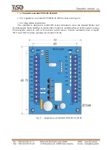
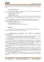
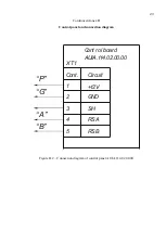
Fig.18
–
Connection of control desk link
cable to terminals PCB.206.21.00.00
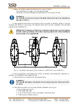
Fig. 17
–
Connection of power supply
cable
12) Turnstile connection:
a) Power supply cable ~230 V to be connected
(
Fig. 17):
-
Phase (L) - to be connected to circuit breaker;
- Neutral (N) to be connected to terminal
~230V;
-
Earth (РЕ) to be connected to earthing
terminal (РЕ).
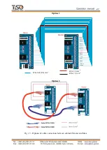
b) Control desk link cable to be connected to
terminals
(Fig.18):
-
P
(Power)
–
control desk power 12V;
-
G
(GND) - control desk common wire;;
-
A
(RSA) - RSA wire control desk link line;
-
B
(RSB) - RSB wire control desk link line;
c) The turnstile to be earthed and power supply
cable to be connected the turnstile according to the
wiring diagrams (See Annex C)
d) Proximity card readers to be installed if
access control system (ACS) is available.
The turnstile doors and side panels (Fig.17 ) to
be installed, on their fixation locations after the
required mounting is completed. Countertop to be
fixed with screws.
13) Installation of proximity card reader
upon availability of access control system
(ACS) See Fig. 19.
1 - The turnstile top lid (a) and interior finishing to be removed;
2 - Screws to be unscrewed and protective screen (acrylate) (b) to be removed. The card
reader (d) bracket (с) to be
adjusted;
3
–
Card reader to be connected to ACS. The maximum dimensions of the identification card
reader (d) to be installed is 80х80х30 mm (See Fig. 19);
4 - Protective screen (b) to be fixed with screws in the previous position. The turnstile lining
and top lid to be installed and fixed with screws in the previous position;
Optional


