36
4)
The turnstile to be energized;
5)
Zero position setting button on magnetic sensor board to be pushed and hold for at least 1
second, then to be released (make sure that the button pressure force does not bend the
board);
6)
After the button on the magnetic sensor board is released the zero position LED to be lit;
7)
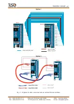
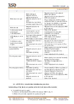
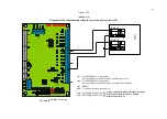
Presence of signals of rotation angle changing, speed and zero position on controller PCB
201 - terminals: IN5, IN6, IN7, IN8. During
blade opening and closing:
- IN5, IN6
–
should exchange winks.
- IN7
–
is lit brightly if the blade is not moved
or is moved slowly. Brightness is decreased if
blade is rotated rapidly.
-
IN8
–
to be lit in just set zero position;
8)
Turnstile to be deenergized;
9)
Motor to be connected to PCB 201, terminals
MOT1;
10)
The turnstile to be energized;
11)
Turnstile operation to be checked
12)
New zero position setting is completed
Leaf initial position calibration (Fig.21).
1)
The initial position setting button on the magnetic sensor board to be pushed (care must be
exercised to avoid the board bending due to the button pushing force);
2)
The new leaf initial position to be set;
3)
The button to be released;
4)
After the button on the magnetic sensor board is released the initial position LED to be lit;
5)
The presence of turning angle, speed and initial position change signals on controller
PCB201 to be checked
–
terminals: IN5, IN6, IN7, IN8. When the leaf is turned:
- IN5, IN6 to be exchanged winks.
- IN7 is lit brightly when leaf is no turned or turned slowly. When it is turned quickly then
bright will be reduced,
- IN8 to be lit only in the set initial position;
6)
The new initial position calibration The new initial position setting is completed.is
completed
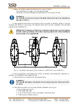
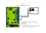
Fig. 21
–
General view of the «JETPAN»turnstile magnetic sensor
Fig. 20
–
Turnstile blade in zero position
(access way is open)
Gap
between magnetic axis and
magnetic sensor
Top view of the installed magnetic
sensor
Layout of board over
magnetic axis


