background image

6.

  Installation of boom barrier

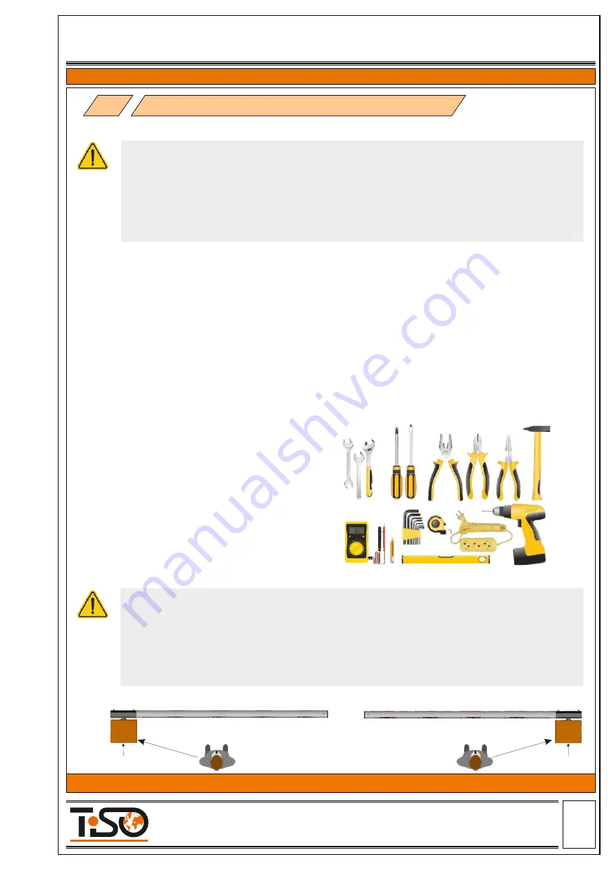
Left version boom barrier

Right version boom barrier 

cabinet door

cabinet door

џ

Arrangement of installation site must comply with requirements of the applicable regulations and 
standards.

џ

Installation area shall be fenced along perimeter with temporary security fencing or  caution tape 
at the distance of 3 meters from the installation site.

џ

The appropriate warning signs ISO 7010:2011 shall be installed in front of the installation site.

џ

Keep outsiders away from the installation site!

џ

Safety regulations must be observed during installation!

6.1 Preliminary check

Make sure that the following conditions are met to ensure safe and reliable operation of the Boom 

Barrier:  

џ

The installation site soil should provide high stability of the base plate.

џ

The boom should not be in contact with foreign objects (e.g. tree branches) along the entire move-
ment and should move at least 2 m apart overhead power transmission lines.

џ

Make sure that there are no underground utilities at the installation site!

џ

No underground pipes and/or cables to be available within the excavation area for the base plate 
installation.

џ

If there is a risk of damage of the Boom Barrier body by passing vehicles, then the required precau-
tionary measures to be taken, if applicable, to protect it from impacts.

џ

The Boom Barrier rack to be securely grounded to ensure electrical safety.

џ

The Boom Barrier installation requires preliminary pulling of electric cables and, if necessary, laying 
of the base plate. 

- if the cabinet is on the right, it is a right version of boom-barrier.

Prior to installation make sure of availability 

of all necessary tools and materials, ensuring the 
system  installation  in  full  accordance  with  the 
applicable safety regulations.

Note to boom barrier installation:

The barrier may be used exclusively for the passage of vehicles. Pedestrians shall not pass under 

a moving arm. A passage suitable for pedestrians should be provided. This passage shall be indicated 
by a special sign;

The cabinet door shall be located on the inside of the territory. If you are in the centre of the pas-

sageway, turn towards the outside:

- if the cabinet is on the left, it means it is a left version of boom-barrier,

6.2 Tools 

The minimum kit of the required installation 

tools is shown in Figure below.

Page

-11-


     Size А4

Installation and Operation Manual

Revision 1.0                     2021

ROAD BLOCKING SYSTEMS


Office and Production site:               


Tel.: 

+380 (44) 291-21-11

 14 Promyslova str., 02088, Kyiv, Ukraine,                                     

Fax:

 +380 (44) 291-21-02

 E-mail:

 sales@tiso.global                                                                              www.tiso.global   


  BOOM BARRIER OPTIMUS 

Summary of Contents for Optimus 40

Page 1: ...N MANUAL PART Original guide Page 1 Size 4 Installation and Operation Manual Revision 1 0 2021 ROAD BLOCKING SYSTEMS Office and Production site Tel 380 44 291 21 11 14 Promyslova str 02088 Kyiv Ukrain...

Page 2: ...Recommended Scope of Delivery 5 3 Boom Barrier mechanism design 5 Product speci cation Contents 4 1 Technical features of boom barrier Optimus 4 Technical Specifications 2 Description 1 General Guidel...

Page 3: ...30 EC 2014 35 EC DECLARATION OF CONFORMITY OF EQUIPMENT Page 3 Size 4 Installation and Operation Manual Revision 1 0 2021 ROAD BLOCKING SYSTEMS Office and Production site Tel 380 44 291 21 11 14 Promy...

Page 4: ...2 The product shall be installed in accordance with applicable regulations and rules in compliance with safety precautions during installation work 3 Installation of the equipment shall be carried out...

Page 5: ...ecurity measures The boom barrier must be installed precommissioned and serviced by the certi ed professionals having the relevant quali cation and being familiar with Manuals and product documentatio...

Page 6: ...proaches to cottages and cottage settlements at central urban and historical sites industrial and special facilities 3 1 The electromechanical barrier Optimus is intended to restrict access to territo...

Page 7: ...RAL9005 Arm barrier material powder coated aluminium RAL 9010 LED indicatiion Double sided RYG light indication in cabinet Raised position locking gear motor Manual operation manual release mechanical...

Page 8: ...mm 308 mm View 306 mm 236 mm 350 mm 13 mm 4 holes 60 mm Cable input 22 mm 150 mm 175 mm 42 mm Page 8 Size 4 Installation and Operation Manual Revision 1 0 2021 ROAD BLOCKING SYSTEMS Office and Produc...

Page 9: ...ost 12 Arm lighting RYG After the Boom Barrier is received it is to be unpacked and inspected to be sure that the Boom Barrier is not damaged If any damage is found then the Road Barrier supplier to b...

Page 10: ...spring 4 Electronic control unit 5 Cabinet lid 6 Cabinet light indication 7 Manual operation emergency release 8 Gear motor 9 Gear motor lever 10 11 Upper and lower arm movement restrictor 12 Magnet 1...

Page 11: ...Barrier body by passing vehicles then the required precau tionary measures to be taken if applicable to protect it from impacts The Boom Barrier rack to be securely grounded to ensure electrical safe...

Page 12: ...the foundation by means of anchor bolts The depth of concreting depends on the softness of soil and on the depth of soil freezing 160 500 mm 1 Dig the ground for concrete base prepare the corrugated...

Page 13: ...n the end positions of the barrier open closed the barrier arm must be strictly vertical and horizontal Alignment is achieved by adjusting the positions of the mechanical stops see clause 6 4 3 2 Pres...

Page 14: ...m balance 6 lock the drive by tightening the screw of lever xing 6 4 2 Arm balancing Check the condition for correct arm balancing spring operation in the vertical arm position the spring is in a free...

Page 15: ...of barrier mechanism lever is limited by stops The boom is correctly adjusted when it is suf ciently stable in the 0 and 90 positions For arm lowering or raising adjust the upper and lower position of...

Page 16: ...power must be connected turn off 230V power supply In cases where there is no electricity Optimus boom barrier models have a manual control mode 6 5 Manual control For manual control of the boom barr...

Page 17: ...Versions of Boom barrier Optimus Left version of boom barrier Arm in a horizontal position in an upright position Sector in the top position in the lowered position Spring compressed uncompressed Rig...

Page 18: ...ted to the circuit breaker Neutral N to be connected to terminal 230V Earth to be connected to earthing terminal b Control panel cable to be connected to terminals P Power control panel power supply 1...

Page 19: ...outside the arm of boom barrier two posts are installed on opposite sides of roadway a transmitter is mounted on one post a sensor receiver is on the other Place the receiver and transmitter of the sa...

Page 20: ...sition until new commands are given Forbidden boom barrier partially closed Close the passage Press the button DOWN The boom barrier will rise to the lowest position and stop Forbidden boom barrier cl...

Page 21: ...s are faulty Check safety sensors replace them if necessary In case of a malfunction which cannot be solved using the information from this Manual contact the service department 9 2 Possible malfuncti...

Page 22: ...le integrity Boom Barrier normal operation without jerks and abnormal noises jamming of movable constructional elements motor heating over 70 C M 1 monthly M 1 is performed monthly and includes the fo...

Page 23: ...which on the boom barrier connection line must be installed 10 3 6 Boom barrier electrical equipment should be earthed Resistance between earthing bus and each accessible metal non current carrying pa...

Page 24: ...o prevent boom barrier raising and sinking to use metalwork of boom barrier for connection of neutral wire of electric welder to perform welding works near the road blocker without noncombustible mate...

Reviews:

Related manuals for Optimus 40