background image

Barrier cabinet

Concrete 
   base

Corrugated pipe for

communications


Anchor redibolt 
М12х165

Concreted
pit

Bottom 
plate

Corrugated pipe for

communications 

Washer and
nut (4 pairs)

Communication 
 input

Cabinet

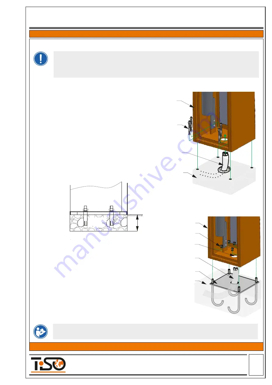
Concreting to be carried out in accordance with existing standards
The required electrical cables must be routed out of the concrete base.

џ

Place the barrier cabinet on the concreted bottom 
plate 

fix 

and 

with nuts.

џ

Level the 

 horizontally with the help of 

bottom plate

the building level;

џ

Concrete the 

;

bottom plate

џ

Install  a  corrugated  pipe  for  communications  for 
laying electrical cables;

џ

Dig a pit for the 

;

bottom plate

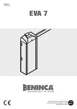
Option 2 - Laying the bottom plate for foundation

4) The Boom Barrier cabinet to be installed and anchor 

nuts to be screwed.

3) 

The cabinet to be oriented correctly, and levelled by 

means  of  builder's  level,  anchor  (M12x165)  holes  for 
high performance concrete expansion to be marked and 
drilled along the perimeter.

2)  The  barrier  cabinet  is  fixed  to  the  foundation  by 

means of anchor bolts. The depth of concreting depends 
on the softness of soil and on the depth of soil freezing 
(160–500 mm).

1)  Dig  the  ground  for  concrete  base,  prepare  the 

corrugated hoses necessary for making connections for 
the subsequent routing of cables in them (the required 
number of channels depends on the type of installation 
and the connected accessories).


Option 1 -Cabinet fastening  

There are two ways to mount a barrier cabinet on the site:

It is recommended to install barrier cabinet in such a way that cabinet door to be opened from the 

protected area.

The ground on the installation site shall be sufficiently stable for installation of boom barrier. If the 

stability of the soil is unsatisfactory, increase the depth of pit as recommended by the specialists. 

6.3 Preparation of bottom plate and installation of barrier cabinet

150-500

Cabinet

±0,000 R.s.l.

Concrete 
    base

Page

-12-


     Size А4

Installation and Operation Manual

Revision 1.0                     2021

ROAD BLOCKING SYSTEMS


Office and Production site:               


Tel.: 

+380 (44) 291-21-11

 14 Promyslova str., 02088, Kyiv, Ukraine,                                     

Fax:

 +380 (44) 291-21-02

 E-mail:

 sales@tiso.global                                                                              www.tiso.global   


  BOOM BARRIER OPTIMUS 

Summary of Contents for Optimus 40

Page 1: ...N MANUAL PART Original guide Page 1 Size 4 Installation and Operation Manual Revision 1 0 2021 ROAD BLOCKING SYSTEMS Office and Production site Tel 380 44 291 21 11 14 Promyslova str 02088 Kyiv Ukrain...

Page 2: ...Recommended Scope of Delivery 5 3 Boom Barrier mechanism design 5 Product speci cation Contents 4 1 Technical features of boom barrier Optimus 4 Technical Specifications 2 Description 1 General Guidel...

Page 3: ...30 EC 2014 35 EC DECLARATION OF CONFORMITY OF EQUIPMENT Page 3 Size 4 Installation and Operation Manual Revision 1 0 2021 ROAD BLOCKING SYSTEMS Office and Production site Tel 380 44 291 21 11 14 Promy...

Page 4: ...2 The product shall be installed in accordance with applicable regulations and rules in compliance with safety precautions during installation work 3 Installation of the equipment shall be carried out...

Page 5: ...ecurity measures The boom barrier must be installed precommissioned and serviced by the certi ed professionals having the relevant quali cation and being familiar with Manuals and product documentatio...

Page 6: ...proaches to cottages and cottage settlements at central urban and historical sites industrial and special facilities 3 1 The electromechanical barrier Optimus is intended to restrict access to territo...

Page 7: ...RAL9005 Arm barrier material powder coated aluminium RAL 9010 LED indicatiion Double sided RYG light indication in cabinet Raised position locking gear motor Manual operation manual release mechanical...

Page 8: ...mm 308 mm View 306 mm 236 mm 350 mm 13 mm 4 holes 60 mm Cable input 22 mm 150 mm 175 mm 42 mm Page 8 Size 4 Installation and Operation Manual Revision 1 0 2021 ROAD BLOCKING SYSTEMS Office and Produc...

Page 9: ...ost 12 Arm lighting RYG After the Boom Barrier is received it is to be unpacked and inspected to be sure that the Boom Barrier is not damaged If any damage is found then the Road Barrier supplier to b...

Page 10: ...spring 4 Electronic control unit 5 Cabinet lid 6 Cabinet light indication 7 Manual operation emergency release 8 Gear motor 9 Gear motor lever 10 11 Upper and lower arm movement restrictor 12 Magnet 1...

Page 11: ...Barrier body by passing vehicles then the required precau tionary measures to be taken if applicable to protect it from impacts The Boom Barrier rack to be securely grounded to ensure electrical safe...

Page 12: ...the foundation by means of anchor bolts The depth of concreting depends on the softness of soil and on the depth of soil freezing 160 500 mm 1 Dig the ground for concrete base prepare the corrugated...

Page 13: ...n the end positions of the barrier open closed the barrier arm must be strictly vertical and horizontal Alignment is achieved by adjusting the positions of the mechanical stops see clause 6 4 3 2 Pres...

Page 14: ...m balance 6 lock the drive by tightening the screw of lever xing 6 4 2 Arm balancing Check the condition for correct arm balancing spring operation in the vertical arm position the spring is in a free...

Page 15: ...of barrier mechanism lever is limited by stops The boom is correctly adjusted when it is suf ciently stable in the 0 and 90 positions For arm lowering or raising adjust the upper and lower position of...

Page 16: ...power must be connected turn off 230V power supply In cases where there is no electricity Optimus boom barrier models have a manual control mode 6 5 Manual control For manual control of the boom barr...

Page 17: ...Versions of Boom barrier Optimus Left version of boom barrier Arm in a horizontal position in an upright position Sector in the top position in the lowered position Spring compressed uncompressed Rig...

Page 18: ...ted to the circuit breaker Neutral N to be connected to terminal 230V Earth to be connected to earthing terminal b Control panel cable to be connected to terminals P Power control panel power supply 1...

Page 19: ...outside the arm of boom barrier two posts are installed on opposite sides of roadway a transmitter is mounted on one post a sensor receiver is on the other Place the receiver and transmitter of the sa...

Page 20: ...sition until new commands are given Forbidden boom barrier partially closed Close the passage Press the button DOWN The boom barrier will rise to the lowest position and stop Forbidden boom barrier cl...

Page 21: ...s are faulty Check safety sensors replace them if necessary In case of a malfunction which cannot be solved using the information from this Manual contact the service department 9 2 Possible malfuncti...

Page 22: ...le integrity Boom Barrier normal operation without jerks and abnormal noises jamming of movable constructional elements motor heating over 70 C M 1 monthly M 1 is performed monthly and includes the fo...

Page 23: ...which on the boom barrier connection line must be installed 10 3 6 Boom barrier electrical equipment should be earthed Resistance between earthing bus and each accessible metal non current carrying pa...

Page 24: ...o prevent boom barrier raising and sinking to use metalwork of boom barrier for connection of neutral wire of electric welder to perform welding works near the road blocker without noncombustible mate...

Reviews: