background image

џ

reflective stickers  for arms

џ

traffic light, etc.

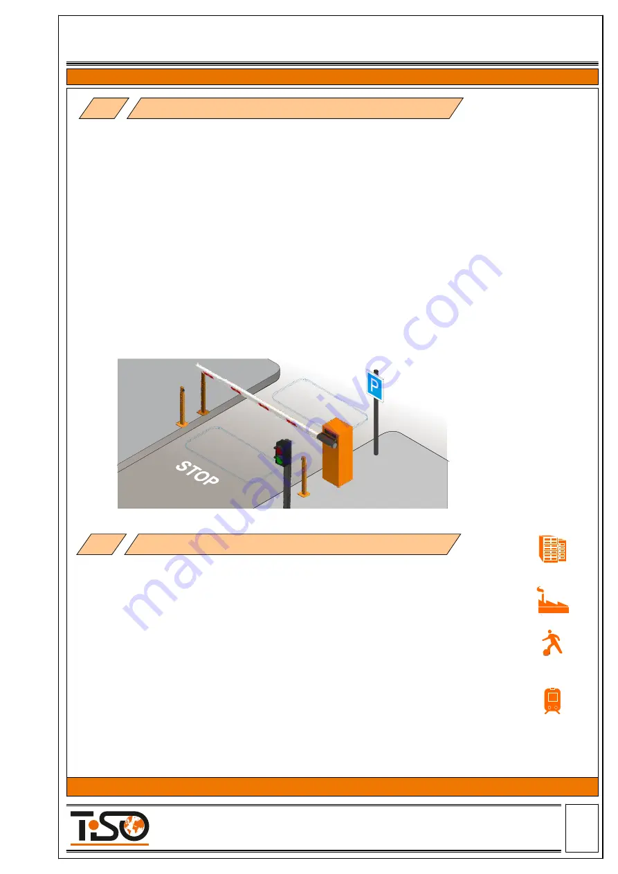
2.1  Electro-mechanical  boom  barrier  “Optimus”  is  intended  for  arrangement  and  control  of  vehicle 

passageway width up to 6m.

2.2 Boom barrier “Optimus” has a reliable simple structure, the main elements of which are a stand with a  

power-operated  mechanism,  an  barrier  arm  and  an  electronic  control  unit.    Boom  barrier  is  balanced  by 
tension/compression of spring and depends on the arm length and accessories installed on it.The drive design 
allows to use a 4m barrier arm without use of support and a 6m barrier arm with a support. 

2.3The barrier may be operated from:

џ

wired or wireless remote control;

џ

automatic access control system (access cards, exit buttons);

џ

manual (in case of power failure the boom barrier can be operated manually)

2.4 Coating -  black and orange paint ;
2.5 A wide range of accessories is available for convenient use:

џ

LED lighting of Barrier arm

џ

IR barriers (safety sensors) 

џ

induction loops 

џ

arm support post 

to sports facilities and governmental facilities, to be installed in front of shops, hotels,shopping 

malls  and  office  centers,  health  care  facilities,  at  the  approaches  to  cottages  and  cottage 
settlements, at central urban and historical sites, industrial and special facilities.

3.1 The electromechanical barrier  “Optimus” is intended to restrict access to territory with 

high traffic intensity and width of passage up to 6 meters. The “Optimus”  barrier is used at state, 
commercial and private facilities to restrict unauthorized entry and exit of   vehicles, to regulate 
and arrange traffic of road transport at facilities and adjacent territories. These can be automated 
parking zones, customs terminals, etc.

          3.2 The Boom Barriers are recommended for passenger transport facilities, in the driveway 

             3.3 The Boom Barriers can be installed along with other traffic control and unauthorized 

access prevention equipment.

           3.4  By impact of environmental factors the Boom Barrier complies with EN 300 019-1-4 

and  is  designed  for  outdoor  operation  in  temperate  conditions  with  permissible  ambient 
temperature - 10°С to +40°С.

2.


Description

3.


Product Purpose

OFFICE

BUILDINGS 

PLANTS 

SPORTS AND

LEISURE CENTERS

HAULAGE

COMPANIES 

P

P

P

PARKING LOTS

Page

-6-


     Size А4

Installation and Operation Manual

Revision 1.0                     2021

ROAD BLOCKING SYSTEMS


Office and Production site:               


Tel.: 

+380 (44) 291-21-11

 14 Promyslova str., 02088, Kyiv, Ukraine,                                     

Fax:

 +380 (44) 291-21-02

 E-mail:

 sales@tiso.global                                                                              www.tiso.global   


  BOOM BARRIER OPTIMUS 

Summary of Contents for Optimus 40

Page 1: ...N MANUAL PART Original guide Page 1 Size 4 Installation and Operation Manual Revision 1 0 2021 ROAD BLOCKING SYSTEMS Office and Production site Tel 380 44 291 21 11 14 Promyslova str 02088 Kyiv Ukrain...

Page 2: ...Recommended Scope of Delivery 5 3 Boom Barrier mechanism design 5 Product speci cation Contents 4 1 Technical features of boom barrier Optimus 4 Technical Specifications 2 Description 1 General Guidel...

Page 3: ...30 EC 2014 35 EC DECLARATION OF CONFORMITY OF EQUIPMENT Page 3 Size 4 Installation and Operation Manual Revision 1 0 2021 ROAD BLOCKING SYSTEMS Office and Production site Tel 380 44 291 21 11 14 Promy...

Page 4: ...2 The product shall be installed in accordance with applicable regulations and rules in compliance with safety precautions during installation work 3 Installation of the equipment shall be carried out...

Page 5: ...ecurity measures The boom barrier must be installed precommissioned and serviced by the certi ed professionals having the relevant quali cation and being familiar with Manuals and product documentatio...

Page 6: ...proaches to cottages and cottage settlements at central urban and historical sites industrial and special facilities 3 1 The electromechanical barrier Optimus is intended to restrict access to territo...

Page 7: ...RAL9005 Arm barrier material powder coated aluminium RAL 9010 LED indicatiion Double sided RYG light indication in cabinet Raised position locking gear motor Manual operation manual release mechanical...

Page 8: ...mm 308 mm View 306 mm 236 mm 350 mm 13 mm 4 holes 60 mm Cable input 22 mm 150 mm 175 mm 42 mm Page 8 Size 4 Installation and Operation Manual Revision 1 0 2021 ROAD BLOCKING SYSTEMS Office and Produc...

Page 9: ...ost 12 Arm lighting RYG After the Boom Barrier is received it is to be unpacked and inspected to be sure that the Boom Barrier is not damaged If any damage is found then the Road Barrier supplier to b...

Page 10: ...spring 4 Electronic control unit 5 Cabinet lid 6 Cabinet light indication 7 Manual operation emergency release 8 Gear motor 9 Gear motor lever 10 11 Upper and lower arm movement restrictor 12 Magnet 1...

Page 11: ...Barrier body by passing vehicles then the required precau tionary measures to be taken if applicable to protect it from impacts The Boom Barrier rack to be securely grounded to ensure electrical safe...

Page 12: ...the foundation by means of anchor bolts The depth of concreting depends on the softness of soil and on the depth of soil freezing 160 500 mm 1 Dig the ground for concrete base prepare the corrugated...

Page 13: ...n the end positions of the barrier open closed the barrier arm must be strictly vertical and horizontal Alignment is achieved by adjusting the positions of the mechanical stops see clause 6 4 3 2 Pres...

Page 14: ...m balance 6 lock the drive by tightening the screw of lever xing 6 4 2 Arm balancing Check the condition for correct arm balancing spring operation in the vertical arm position the spring is in a free...

Page 15: ...of barrier mechanism lever is limited by stops The boom is correctly adjusted when it is suf ciently stable in the 0 and 90 positions For arm lowering or raising adjust the upper and lower position of...

Page 16: ...power must be connected turn off 230V power supply In cases where there is no electricity Optimus boom barrier models have a manual control mode 6 5 Manual control For manual control of the boom barr...

Page 17: ...Versions of Boom barrier Optimus Left version of boom barrier Arm in a horizontal position in an upright position Sector in the top position in the lowered position Spring compressed uncompressed Rig...

Page 18: ...ted to the circuit breaker Neutral N to be connected to terminal 230V Earth to be connected to earthing terminal b Control panel cable to be connected to terminals P Power control panel power supply 1...

Page 19: ...outside the arm of boom barrier two posts are installed on opposite sides of roadway a transmitter is mounted on one post a sensor receiver is on the other Place the receiver and transmitter of the sa...

Page 20: ...sition until new commands are given Forbidden boom barrier partially closed Close the passage Press the button DOWN The boom barrier will rise to the lowest position and stop Forbidden boom barrier cl...

Page 21: ...s are faulty Check safety sensors replace them if necessary In case of a malfunction which cannot be solved using the information from this Manual contact the service department 9 2 Possible malfuncti...

Page 22: ...le integrity Boom Barrier normal operation without jerks and abnormal noises jamming of movable constructional elements motor heating over 70 C M 1 monthly M 1 is performed monthly and includes the fo...

Page 23: ...which on the boom barrier connection line must be installed 10 3 6 Boom barrier electrical equipment should be earthed Resistance between earthing bus and each accessible metal non current carrying pa...

Page 24: ...o prevent boom barrier raising and sinking to use metalwork of boom barrier for connection of neutral wire of electric welder to perform welding works near the road blocker without noncombustible mate...

Reviews: