


15
2.2. Troubleshooting
Table 12
–
Troubleshooting
Item
Malfunction
Possible cause
Action
1
Boom
Barrier
is
neither
raised
nor
sunk when
raising
or
lowering
command
is issued
Boom
Barrier
motor
B2-
А1.
Motor
is not connected or
connected improperly to control
unit
Connections to be verified according to
description and diagrams in
Annex 1
and
Annex 2
as well as errors to be
eliminated and connection to be made
properly
Boom
Barrier
end
position
sensors
Sensor TOP or Sensor
BOT
are connected improperly
Connections of, LED displays
LED22
(TOP1), LED23 (BOT1)
to be checked
according to diagrams in
Annex 1
and
Annex 2
and
Table 12
as well as errors
to be eliminated and connection to be
made properly
2
Continuous operation
of
motor
after
reaching
UP
and
DOWN position by
Boom Barrier
End position sensors
Sensor
TOP
or
Sensor BOT
are not
connected, connected improperly
or unadjusted
Connections of, LED displays
LED22
(TOP1), LED23 (BOT1)
to be checked
according to
Annex 1
and
Annex 2
as
well as errors to be eliminated and
connection to be made properly
3
Boom Barrier audio
or visual alarm is
inoperative
Boom Barrier audio or visual
alarm
is
not
connected
or
connected improperly
Connections to be checked according
to diagrams in
Annex 1
and
Annex 2
as well as errors to be eliminated and
connection to be made properly
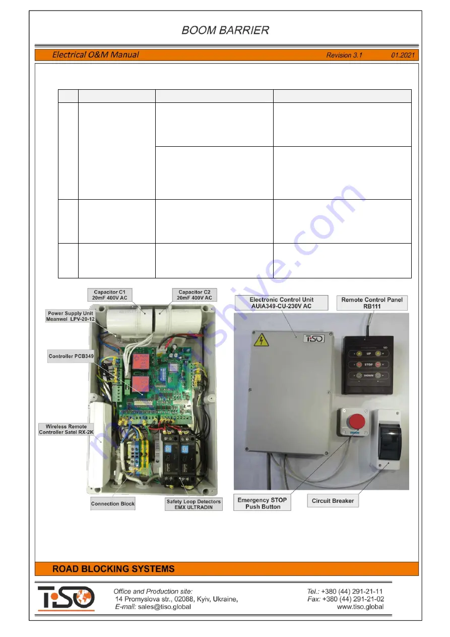
Fig 6 -
Boom Barrier Control Unit
Fig. 7
- The Boom Barrier control unit with remote
control unit RB111, emergency stop button and ON/OFF
switch


