


17
3.2. Boom Barrier wireless control
The Boom Barrier control unit may include additional option
–
Boom Barrier
wireless control by remote
control pendants
.
In this case control unit includes
B3-A3. Wireless Remote Controller Satel RE-2K *
and scope of
delivery includes some remote control pendants
Satel T-2
.
Maximum allowable distance from remote control pendant to control unit is
25 m
.
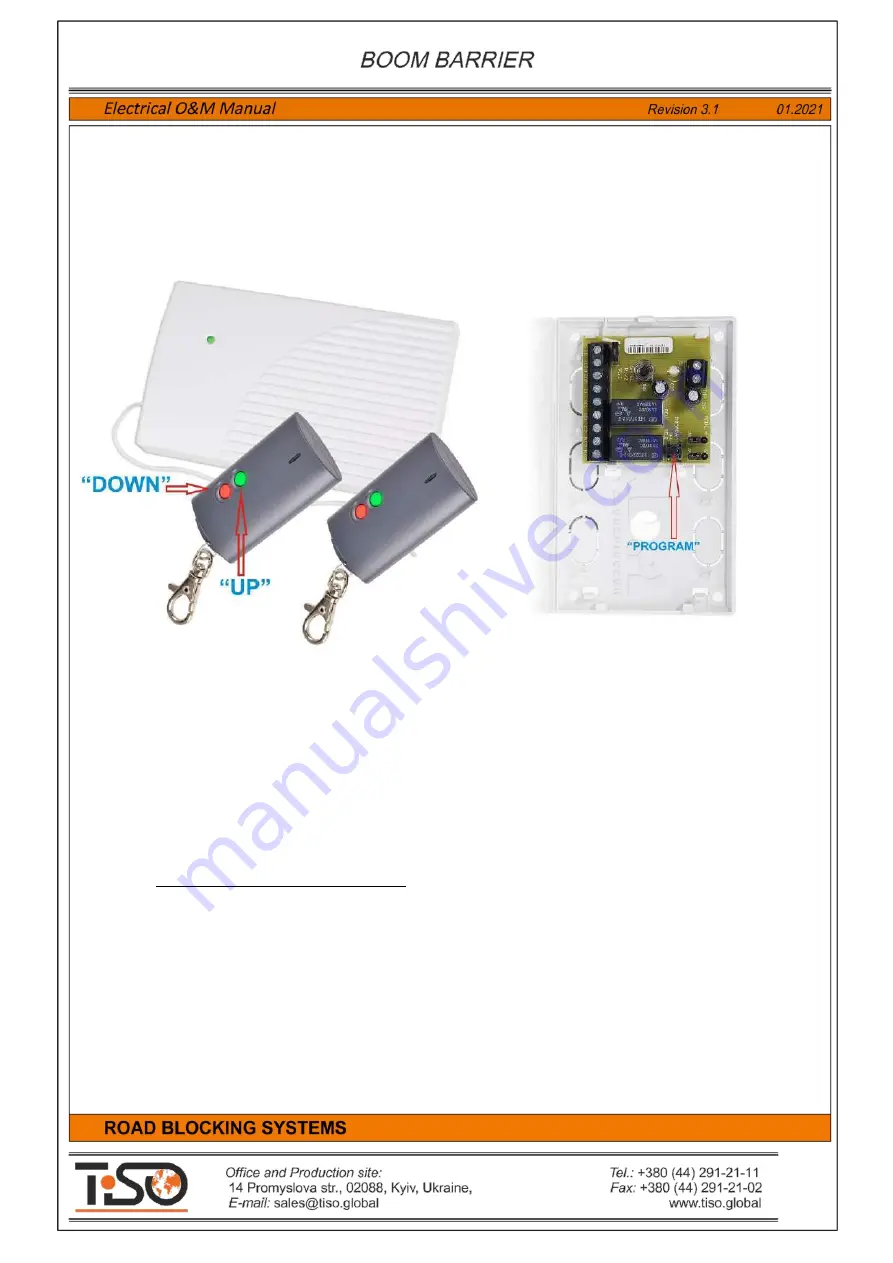
Fig. 9 -
Wireless controller
Satel RE-2K
and remote control pendants
Satel T-2
.
Green
"UP"
button of remote control pendant
Satel T-2
to be pushed to
raise
the road blocker.
Red
"DOWN"
button of remote control pendant
Satel T-2
to be pushed to
sink
the road blocker.
To add new remote control pendants
Satel T-2
in storage of wireless controller
Satel RE-2K
it is
necessary to open top lid and:
1. Programming button
"PROGRAM"
to be pushed
–
LED of wireless controller Satel RE-2K
starts blinking green.
2. Any button of remote control pendant to be pushed
–
LED starts blinking red.
3. Button of remote control pendant to be repushed
–
LED is lit green.
Remote control pendant is added.
More details on wireless controller
Satel RE-2K
can be found on the manufacturer's website by
reference: https://www.satel.pl/en/produktid/483 .


