background image


24 


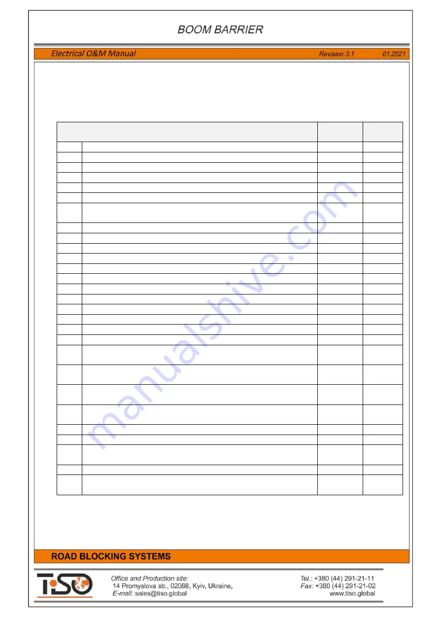
6. List of replacement components in case of failure 

A  list  of  components  with  specified  equivalents,  which  can  replaced  by  certified  service  department  in 

case of failure, is shown in Table 14. 


Table 14 - 

List of replacement components in case of failure 

Position 

Possible 

replacement  

Quantity 

Push Button "Stop" ASCO XAL-J174 


Remote Control Unit RB111 


Circuit Breaker ABB DS 951 AC-B16/0,03A 


Heater Fandis RACMV-400 


Thermostat Fandis TRT-10A230V-NO 


Plastic Case Z95J Kradex (95х190х280)


Universal Controller PCB349.003 - AB-1.0 - Special version for Arm 
Barrier 


Power Supply Unit Mean Well LPV-20-12  (LPV-35-12) 


Capacitor 400V 20uF 


10 

Connector NX5081-02PFS 5.08 mm (2-pin) 


11 

Connector NX5081-03PFS 5.08 mm (3-pin) 


12 

NX5081-TF - Pin for 5,08mm Connector  


13 

Connector WAGO 264-336 


14 

Connector WAGO 264-354 


15 

Connector WAGO 264-357 


16 

Connector WAGO 264-361 


17 

Thermostat KSD9700-5A60-A-K-Plastik 


18 

Fan 120x120x25, 12V (GT2-7015 12VDC) 


19 

LED Strip 5050-60-IP65-RGB-10-

12 RN6060AQ (8147) RISHANG, м


 7 m  

20 

Mini Fit - Connector N42G-04 - Plug; wire-wire; male; N42G; 4.2mm; 
PIN: 4; 


21 

Mini Fit - N42G-

T1  Contact; male; 0.32÷0.82mm2; 22AWG÷18AWG; 

tinned; 9A 


22 

Mini Fit - N42W-04 Plug; wire-wire/PCB; female; N42W; 4.2mm; PIN: 
4; w/o contacts; 


23 

Mini Fit - N42W-

T1 Contact; female; 0.32÷0.82mm2; 

22AWG÷18AWG; tinned; crimped; 9A


24 

Magnetic Reed Switch 5С

-51 


25 

Super Magnet - 10 x 5 x 5   N42 


26 

Radio Control Set Satel RE-2K 2-channel, Radio Cont 2 
Keyfobs in set, pc 


27 

DIN Rail Mount Vehicle Loop Detector - EMX ULTRALOOP ULT-DIN 


1 or 2 

28 

Cable ÖLFLEX® HEAT 180 SiF 1х1.0 for Inductive Loop realization


30m or 

more 

Summary of Contents for Optimus RB392 Series

Page 1: ......

Page 2: ...eration 13 2 2 Troubleshooting 15 3 1 Wire remote control panel RB111 16 3 2 Boom Barrier wireless control 17 3 3 Protective induction loops 18 4 Road Blocker operator s guide 21 5 Boom Barrier electr...

Page 3: ...control unit is a controller with additional electric parts and is designed to control the Boom Barrier The control unit is assembled in a plastic box and is located inside the Boom Barrier rack Powe...

Page 4: ...4 1 2 Description of the versatile controller PCB349 Fig 2 Illustration of controller PCB349 with identification of its components inputs and outputs...

Page 5: ...inal block for connection of the Road Blocker 1 control inputs sensors and additional devices 9 Terminal block X6 OUT1 Outputs 1 Terminal block for connection of the Road Blocker 1 actuating devices a...

Page 6: ...onnection of neutral N of the Road Blocker1 motor 10 MOTOR 1 PE Output for connection of protective earthing PE of the Road Blocker1 motor When the road blockers are used with peripheral hydraulic uni...

Page 7: ...of DOWN position sensor The Road Blocker will stop when it is activated during lowering When the input is active then it will not respond to lowering command 23 INP SENSOR 3 1 Input for connection of...

Page 8: ...d during lowering When the input is active then it will not respond to lowering command 53 INP SENSOR 3 2 Input for connection of pressure valve It is used only in the road blockers with accumulator 5...

Page 9: ...th accumulator 36 INDICATION LED 1 Output for connection of the Road Blocker 1 additional LED 1 display module anode 37 INDICATION LED 1 Output for connection of the Road Blocker1 additional LED 1 dis...

Page 10: ...r voltage of remote control panel DI 601 39 RS485 A1 Signal RS485 A of angular position sensors DI 601 40 RS485 B1 Signal RS485 B of angular position sensors DI 601 41 GND Common wire GND of angular p...

Page 11: ...sensors induction loops or safety photocells 25 26 55 56 INP Safety When the switch is OFF then road blocker will be stopped when signal is coming on INP Safety When the switch is ON then road blocker...

Page 12: ...econds selected by the TIME1 after each raise or lower command and will stop after this timeout has been completed The timeout of raising and lowering increases when the regulators is rotate clockwise...

Page 13: ...lights external siren are connected to control unit General connection diagram of the Boom Barrier and additional devices is shown in Annex 1 Wiring diagram of the Boom Barrier with control unit and a...

Page 14: ...lowering are determined by the of the position sensors position limit switches and magnets If appropriate end position sensors to be adjusted according to the diagram shown in Fig 5 Fig 5 Adjustment...

Page 15: ...well as errors to be eliminated and connection to be made properly 2 Continuous operation of motor after reaching UP and DOWN position by Boom Barrier End position sensors Sensor TOP or Sensor BOT ar...

Page 16: ...ar DOWN button will be blinking during lowering When Road blocker reaches the lowermost position and stops then the lamp near DOWN button will be steadily lit DOWN position display Road blocker is sto...

Page 17: ...pendant Satel T 2 to be pushed to raise the road blocker Red DOWN button of remote control pendant Satel T 2 to be pushed to sink the road blocker To add new remote control pendants Satel T 2 in stor...

Page 18: ...for preparation of induction loops The maximum allowable distance from induction loop to control unit is 20 m Induction loop responds to vehicle metal and at its location there should not be metal in...

Page 19: ...20 6 10m 3 3 2 0 975m 4 1 22m 22 6 71m 3 3 2 0 975m 4 1 22m 24 7 32m 3 3 2 0 975m 4 1 22m 26 7 93m 3 3 2 0 975m 4 1 22m 28 8 54m 3 3 2 0 975m 4 1 22m 30 9 14m 2 3 2 0 975m 4 1 22m 32 9 75m 2 3 2 0 97...

Page 20: ...s of cable SIF1 0 of each induction loop to be connected to terminals LOOP and LOOP of Safety Loop Detector EMX ULTRADIN induction loop controller of control unit Fig 11 Diagram of connection of induc...

Page 21: ...dependent road blockers connected to one control unit The Road Blocker wireless control pendant Satel RE 2K is equipped only with buttons UP and DOWN but is not equipped with button STOP The operator...

Page 22: ...rgency stop button Emergency Stop When this button is pushed then the Boom Barrier will be stopped and will be standstill until it is released and new commands UP or DOWN are generated When the button...

Page 23: ...damages of the Boom Barrier to be visually inspected Integrity of circuit of protective earthing P of Boom Barrier metal parts with circuit of earthing P of power supply network earthing circuit resis...

Page 24: ...X5081 03PFS 5 08 mm 3 pin 1 12 NX5081 TF Pin for 5 08mm Connector 6 13 Connector WAGO 264 336 1 14 Connector WAGO 264 354 1 15 Connector WAGO 264 357 1 16 Connector WAGO 264 361 1 17 Thermostat KSD970...

Page 25: ...25 Annex 1 Boom Barrier Connection Diagram...

Page 26: ...26 Annex 2 Wiring Diagram of Boom Barrier with additional devices...

Reviews: