background image


1.2.1 Description of the PCB349 controller components 
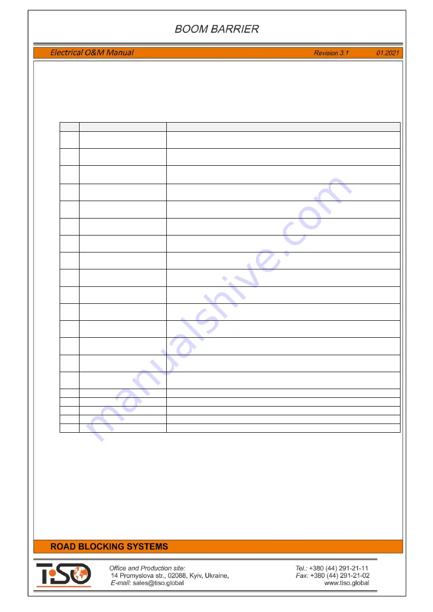
 
The  controller 

PCB349

  controls  operation  of  devices  by  analyzing  signals  from potential  inputs,  angular 

position  sensors  and  wire  pushbutton  control  panel  connected  via  interface 

RS485

  and  sets  potential  outputs 

depending on the Road Blocker status. 

Table 1 

contains description of the 

PCB349 

controller components 

Item 

Component 

Purpose 

Terminal block 

X1 PS


Power Supply  230V AC


Terminal block  for   connection of controller 

supply voltage  

230VAC


Terminal block 

X2 M1


Motor 1 

 Terminal block for connection of the Road Blocker1 built-in 

hydraulic unit motor 

Terminal block 

X3 M2


Motor  2 

  Terminal  block  for  connection  of  the  Road  Blocker2 

built-in hydraulic unit motor 

Fuse 

F1


Fuse  1 

Fuse 

6A  250VAC 

of  the  Road  Blocker1  mini  hydraulic  unit 

motor 

Fuse 

F2


Fuse  2 

 Fuse 

6A  250VAC 

of the Road Blocker2  mini hydraulic unit 

motor 

Terminal block 

С1


Capacitor  1 

  Terminal  block  for  connection  of  the  Road  Blocker1 

mini hydraulic unit capacitor 

С1


Terminal block 

С2


Capacitor  2 

  Terminal  block  for  connection  of  the  Road  Blocker2 

mini hydraulic unit capacitor 

С

2


Terminal block 

X5 INP1


Inputs  1 

  Terminal  block  for  connection  of  the  Road  Blocker  1  

control inputs, sensors and additional devices 

Terminal block 

X6 OUT1


Outputs  1 

  Terminal  block  for  connection  of  the  Road  Blocker  1 

actuating devices and additional devices 

10 

Terminal block 

X7 INP2


Inputs  2 

  Terminal  block  for  connection  of  the  Roa d  Block er 2 

control inputs, sensors and additional devices 

11 

Terminal block 

X8 OUT2


Outputs  2 

  Terminal  block  for  connection  of  the  Road  Blocker  2 

actuating devices and additional devices 

12 

Terminal block 

X9 RS485


Interface  RS485 

  Terminal  block  for  connection  of  the  Road 

Blocker 1 and 2 remote control panel and angular position sensors 

13  Terminal block 

X4 230V 

TO PSU


230V  to  Power  Supply  Unit 

    Terminal  block  for  connection  of  the 

power supply unit voltage 

230VAC


14  Terminal block  

X10. 12V from PSU


12V  DC  from  Power  Supply  Unit 

  Terminal  block for  connection  of 

the power supply unit voltage 

12VDC


15 

Switch 

SW1- SW8


Switch  1-8 

  Switch  of  the  control  unit  mode  and  configuration 

parameter  setting 

16 

Displays 

LED1-LED8


Displays of  mode and configuration parameters 

17 

Displays 

LED18-LED26


Displays of the Road Blocker1 input 

INP1 

status 

18 

Displays 

LED9-LED17


Displays of  the Road Blocker2 input 

INP2 

status 

19 

Displays 

LED33-LED38


Displays of  the Road Blocker1 output 

OUT1 

status 

20 

Displays 

LED27-LED32


Displays of  the Road Blocker2 output 

OUT2 

status 


Summary of Contents for Optimus RB392 Series

Page 1: ......

Page 2: ...eration 13 2 2 Troubleshooting 15 3 1 Wire remote control panel RB111 16 3 2 Boom Barrier wireless control 17 3 3 Protective induction loops 18 4 Road Blocker operator s guide 21 5 Boom Barrier electr...

Page 3: ...control unit is a controller with additional electric parts and is designed to control the Boom Barrier The control unit is assembled in a plastic box and is located inside the Boom Barrier rack Powe...

Page 4: ...4 1 2 Description of the versatile controller PCB349 Fig 2 Illustration of controller PCB349 with identification of its components inputs and outputs...

Page 5: ...inal block for connection of the Road Blocker 1 control inputs sensors and additional devices 9 Terminal block X6 OUT1 Outputs 1 Terminal block for connection of the Road Blocker 1 actuating devices a...

Page 6: ...onnection of neutral N of the Road Blocker1 motor 10 MOTOR 1 PE Output for connection of protective earthing PE of the Road Blocker1 motor When the road blockers are used with peripheral hydraulic uni...

Page 7: ...of DOWN position sensor The Road Blocker will stop when it is activated during lowering When the input is active then it will not respond to lowering command 23 INP SENSOR 3 1 Input for connection of...

Page 8: ...d during lowering When the input is active then it will not respond to lowering command 53 INP SENSOR 3 2 Input for connection of pressure valve It is used only in the road blockers with accumulator 5...

Page 9: ...th accumulator 36 INDICATION LED 1 Output for connection of the Road Blocker 1 additional LED 1 display module anode 37 INDICATION LED 1 Output for connection of the Road Blocker1 additional LED 1 dis...

Page 10: ...r voltage of remote control panel DI 601 39 RS485 A1 Signal RS485 A of angular position sensors DI 601 40 RS485 B1 Signal RS485 B of angular position sensors DI 601 41 GND Common wire GND of angular p...

Page 11: ...sensors induction loops or safety photocells 25 26 55 56 INP Safety When the switch is OFF then road blocker will be stopped when signal is coming on INP Safety When the switch is ON then road blocker...

Page 12: ...econds selected by the TIME1 after each raise or lower command and will stop after this timeout has been completed The timeout of raising and lowering increases when the regulators is rotate clockwise...

Page 13: ...lights external siren are connected to control unit General connection diagram of the Boom Barrier and additional devices is shown in Annex 1 Wiring diagram of the Boom Barrier with control unit and a...

Page 14: ...lowering are determined by the of the position sensors position limit switches and magnets If appropriate end position sensors to be adjusted according to the diagram shown in Fig 5 Fig 5 Adjustment...

Page 15: ...well as errors to be eliminated and connection to be made properly 2 Continuous operation of motor after reaching UP and DOWN position by Boom Barrier End position sensors Sensor TOP or Sensor BOT ar...

Page 16: ...ar DOWN button will be blinking during lowering When Road blocker reaches the lowermost position and stops then the lamp near DOWN button will be steadily lit DOWN position display Road blocker is sto...

Page 17: ...pendant Satel T 2 to be pushed to raise the road blocker Red DOWN button of remote control pendant Satel T 2 to be pushed to sink the road blocker To add new remote control pendants Satel T 2 in stor...

Page 18: ...for preparation of induction loops The maximum allowable distance from induction loop to control unit is 20 m Induction loop responds to vehicle metal and at its location there should not be metal in...

Page 19: ...20 6 10m 3 3 2 0 975m 4 1 22m 22 6 71m 3 3 2 0 975m 4 1 22m 24 7 32m 3 3 2 0 975m 4 1 22m 26 7 93m 3 3 2 0 975m 4 1 22m 28 8 54m 3 3 2 0 975m 4 1 22m 30 9 14m 2 3 2 0 975m 4 1 22m 32 9 75m 2 3 2 0 97...

Page 20: ...s of cable SIF1 0 of each induction loop to be connected to terminals LOOP and LOOP of Safety Loop Detector EMX ULTRADIN induction loop controller of control unit Fig 11 Diagram of connection of induc...

Page 21: ...dependent road blockers connected to one control unit The Road Blocker wireless control pendant Satel RE 2K is equipped only with buttons UP and DOWN but is not equipped with button STOP The operator...

Page 22: ...rgency stop button Emergency Stop When this button is pushed then the Boom Barrier will be stopped and will be standstill until it is released and new commands UP or DOWN are generated When the button...

Page 23: ...damages of the Boom Barrier to be visually inspected Integrity of circuit of protective earthing P of Boom Barrier metal parts with circuit of earthing P of power supply network earthing circuit resis...

Page 24: ...X5081 03PFS 5 08 mm 3 pin 1 12 NX5081 TF Pin for 5 08mm Connector 6 13 Connector WAGO 264 336 1 14 Connector WAGO 264 354 1 15 Connector WAGO 264 357 1 16 Connector WAGO 264 361 1 17 Thermostat KSD970...

Page 25: ...25 Annex 1 Boom Barrier Connection Diagram...

Page 26: ...26 Annex 2 Wiring Diagram of Boom Barrier with additional devices...

Reviews: