


8
Table 6
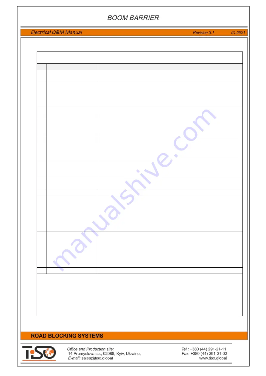
contains description of terminal block
X7. INP2
The Road Blocker2
control inputs, sensors and additional devices to be connected to terminal block
X7. INP2
–
Inputs 2
.
Item
Terminal name
Purpose
46
INP "UP" 2
The Road Blocker raising input. The Road Blocker will start raising
when it is activated.
47
INP "STOP" 2
The Road Blocker stop input. The Road Blocker will stop when
activated. When the input is active, then the Road Blocker will be in
stop status. It has the highest priority and is used for connection of
"Stop" button B5. Remote Emergency Push Button "Stop"
48
INP "DOWN" 2
The Road Blocker lowering input. The Road Blocker will start lowering
when it is activated.
49
INP "FORSE" 2
The Road Blocker rapid raising input. The Road Blocker will start
raising with maximum speed when activated.
It is used only in the road blockers with accumulator.
50
GND
Common wire GND.
51
INP "SENSOR TOP 2"
Input for connection of UP position sensor. The Road Blocker will stop
when it is activated during raising. When the input is active, then it will
not respond to raising command. .
52
INP "SENSOR BOT 2"
Input for connection of DOWN position sensor. The Road Blocker will
stop when it is activated during lowering. When the input is active,
then it will not respond to lowering command.
53
INP "SENSOR 3" 2
Input for connection of pressure valve.
It is used only in the road blockers with accumulator.
54
GND
Common wire GND.
55
INP "SAFETY 1" 2
Protective entry sensor input. Induction loop controller or entry safety
Photocell to be connected to the input.
It is designed to prevent the road blocker raising, when a vehicle is
found on it.
The road blocker will stop or will start lowering when it is activated
during raising. Response type is selected by the switch SW1.7.
56
INP "SAFETY 2" 2
Protective exit sensor input. Induction loop controller or exit safety
photocell to be connected to the input.
It is designed to prevent the Road Blocker raising, when a vehicle is
found on it. The Road Blocker will stop or will start lowering when it is
activated during raising. Response type is selected by the switch
SW1.7
57
GND
Common wire GND.
All inputs
INP2
include similar interface and are compatible with outputs of
"dry contact"
or
"open collector"
type.
The input is active when it is connected to one of common wires
GND
.
It is inactive when it is not connected to
GND
Status of inputs
INP2
is indicated by displays
LED9-LED17
located next to them.
Connection to the terminal block
INP2
is performed via the additional intermediate terminal block
B3-
TX2. Connection blocks INP2 Wago 260
.


