


9
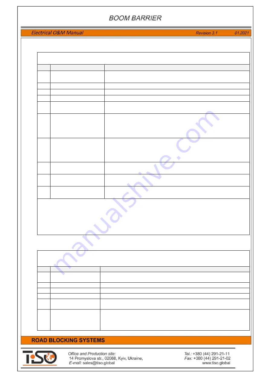
Table 7
contains description of terminal block
X6. OUT1
The Road Blocker1
actuating and additional devices to be connected to terminal block
X6. OUT1
–
Outputs 1
.
Item
Terminal name
Purpose
28
+12VDC
+12VDC
power voltage output for energization of actuating and
additional devices.
29
INDICATION RED 1
Output for connection of the Road Blocker1
red
display module.
30
INDICATION GREEN 1
Output for connection of the Road Blocker1
green
display module.
31
SOUND 1
Output for connection of the Road Blocker1
siren
.
32
+12VDC
+12VDC
power voltage output for energization of actuating and
additional devices.
33
TRAF. L. TOP OUT 1
The Road Blocker1
UP position
output.
It is active when the Road Blocker1 is in UP position.
It is inactive when the Road Blocker1 is not in UP
position. It can be used by access control system.
34
TRAF. L. BOT OUT 1
The Road Blocker1
DOWN position
output.
It is active when the Road Blocker1 is in DOWN position.
It is inactive when the Road Blocker1 is not in DOWN position.
It can be used by access control system or for traffic light relay control.
35
OUT 1
The Road Blocker1
accumulator valve
control output.
It is used only in the road blockers with accumulator.
36
+ INDICATION LED 1
Output for connection of the Road Blocker 1 additional
LED 1
display
module
anode "+"
37
- INDICATION LED 1
Output for connection of the Road Blocker1 additional
LED 1
display
module
cathode "-"
.
All outputs but
INDICATION LED
include similar interface of
"open collector"
type.
The load capacity of outputs
29. INDICATION RED 1, 30. INDICATION GREEN 1, 31. SOUND 1
is
1,5А.
The load capacity of outputs
33. TRAF. L. TOP OUT 1, 34. TRAF. L. BOT OUT 1, 35. SOUND 1
is
0,2
А.
The output status is indicated by displays
LED18-LED26
located next to them.
Table 8
contains description of terminal block
X8. OUT2
The Road Blocker 2 actuating and additional devices to be connected to terminal block
X8.
OUT2
–
Outputs 2
.
Item
Terminal name
Purpose
58
+12VDC
+12VDC
power voltage output for energization of actuating and
additional devices.
59
INDICATION RED 2
Output for connection of the Road Blocker2
red
display module.
60
INDICATION GREEN 2
Output for connection of the Road Blocker2
green
display module.
61
SOUND 2
Output for connection of the Road Blocker2
siren
.
62
+12VDC
+12VDC power voltage output for energization of actuating and
additional devices.
63
TRAF. L. TOP OUT 2
The Road Blocker 2
UP position
output.
It is active when the Road Blocker2 is in UP position.
It is inactive when the Road Blocker1 is not in UP position. It can be used
by access control system.


