


21
4. Road Blocker operator's guide
The Boom Barrier can be controlled from operator control station, ordinary fixed pushbutton control box,
6-button control panel
RB111
or wireless control pendant
Satel RE-2K
.
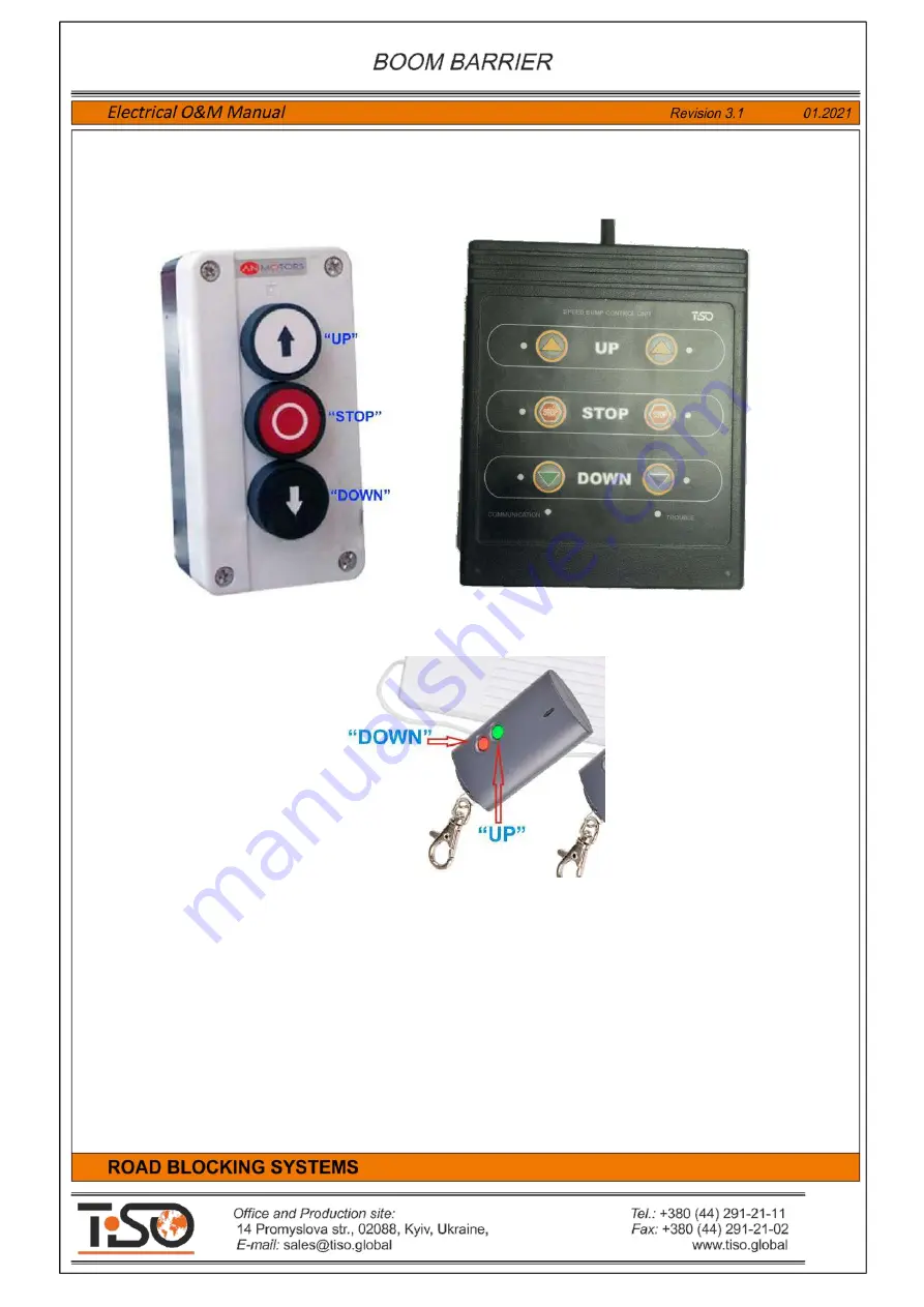
Fig.12 -
Ordinary fixed pushbutton control box (on the left) and 6-button control panel
RB111
(on the right).
Fig. 13
- . Wireless control pendant
Satel RE-2K
.
Control boxes are equipped with buttons
"UP"
,
"STOP"
,
"DOWN"
.
Control panel
RB111
is equipped with two groups of buttons
"UP 1", "STOP 1", "DOWN 1"
and
"UP 2",
"STOP 2", "DOWN 2"
to control two independent road blockers connected to one control unit.
The Road Blocker wireless control pendant
Satel RE-2K
is equipped only with buttons
"UP"
and
"DOWN"
, but is not equipped with button
"STOP"
.
The operator shall push button
"UP"
on control panel to
raise
the Boom Barrier. In this case Boom
Barrier will be raised to the uppermost position and will be stopped.
The operator shall push button
"DOWN"
on control panel to
sink
the Boom Barrier. In this case the Boom
Barrier will be sunk to the lowermost position and will be stopped.
The operator shall push button
"STOP"
on control panel to
stop
the Boom Barrier during raising or
lowering. In this case the Boom Barrier will be stopped and will be standstill until new commands are generated.


