10 AUIA.123.00.00.00.00-05 OM
Controller supply voltage
(10 27)V
Consumption current when outputs «MOT1» and «МОТ2» are OFF
≤0,15 А
Climatic modification and placement category of according to
the GOST 15150-69
NF4
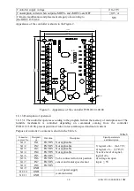
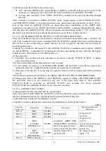
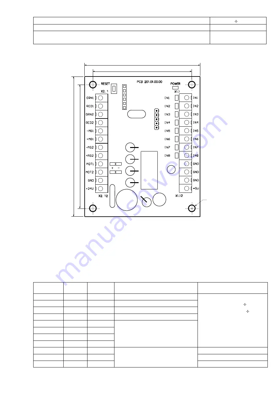
Appearance of the controller is shown in the Figure 2.
Figure 2 – Appearance of the controller РСВ.201.01.00.00
1.8.1.3 Description of operation
1.8.1.3.1 The controller operates according to the program fed into the memory of microprocessor. The
turnstile mechanism is controlled depending on commands coming from the controller
РСВ.112.21.20.00, present position of rotor, rotor rotation speed and motor current.
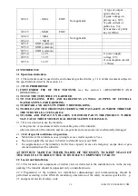
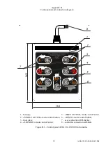
Purpose of controller’s contacts is shown in the Table 6.
Table 6
Connector/
contact No
Designati
on
Direction
Description
Signal parameters
and description
X1/1
IN1
ENTRY
Not applicable
1) logical «0» – (0 1,7)V;
2) logical «1» – (3,7 5)V;
3) active level of signal –
logical «0»;
4) voltage on open
input ≤ 5V
X1/2
IN2
ENTRY
Not applicable
X1/3
IN3
ENTRY
Not applicable
X1/4
IN4
ENTRY
Not applicable
X1/5
IN5
ENTRY
To be connected to rotor position
sensor and motor speed sensor
X1/6
IN6
ENTRY
X1/7
IN7
ENTRY
X1/8
IN8
ENTRY
X1/9
GND
«-» of power supply
(common wire)
X1/10
GND
X1/11
GND
X3.1
X3.5
70 mm
60 mm
7
5
m
m
8
5
m
m
O4 mm


