17 AUIA.123.00.00.00.00-05 OM
2.2.3 The turnstile is installed in the following order:
–
inspect the turnstile for integrity, absence of visual damages and defects;
–
verify the turnstile’s completeness;
–
prepare installation site for mounting of ready-to-install turnstile: surface should be plain, hard and
without defects (corrugations, overlaps etc.);
–
protective ducts or conduits should be laid to the center of the turnstile’s rotor and to installation
sites of power supply units and to control sites to pull power and control cables of the turnstile;
–
mark the hole drilling places and check the marking according to the Appendix A. For this
purpose it is necessary to install the turnstile rotor and enclosures and make sure that the holes on
flanges match the floor or foundation holes. Modify the marking, if required.
The turnstile should be installed and fixed only after all the turnstile electric connection cables are
pulled. For access to fixation holes (see the Figure 1) it is necessary to remove sheeting, fix the
turnstile by means of Redibolt (anchor with jacket and screw) and make sure that the installed turnstile
is stable;
–
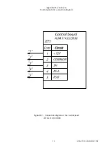
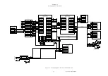
earthen the turnstile, connect power cable to the turnstile and control panel according to the wiring
diagram (see the Appendix C).
After the required installation sheeting should be placed back.
2.3 Preparation for use
2.3.1 Commissioning instructions
Prior to energizing of the turnstile:
1) make sure of proper connection and good condition of all connecting cables;
2) clear the area of the turnstile’s blades rotation from foreign particles.
3) check revolving of rotor: rotor with blades should revolve smoothly and after revolving to 120° it
should be locked.
When mains cable of power supply unit is connected to the network the flag rotation is locked. The
turnstile is set in initial state. Flag with blades is locked from rotation in both directions and access
between enclosures is barred by one of the blades.
The turnstile is set in initial state: entry and exit LED displays are red («
›‹
» is lit)
1
.
2.3.2 Required inspections
2.3.2.1 When rotor turnstile is commissioned as part of Access Control System or when it is controlled
by means of control panel (complete with reader racks and LED display panel) it is necessary to
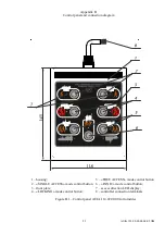
perform inspections specified in the Table 9. During inspections the wiring diagram according to the
Appendix C and the control panel according to the Appendix B should be used.
Table 9
Operating Mode
Mode Setting
LED Display
1
Functional Check
1 Turnstile is closed
in both directions
(initial state)
–
Red LED display is lit
Make sure that rotor can’t be
rotated in any direction
2 Single access in
one direction
Push the
«SINGLE» access
button to access
in chosen
direction
(«A» or «B»)
Green arrow of single
access is lit in chosen
direction and red LED
display is lit in
opposite direction
Make sure that in case of
gentle push in the direction of
authorized access rotor starts
rotating and stops after rotation
to 120º.
Rotor should not start rotation
independently
3 Single access in
both directions
Push both
«SINGLE»
access buttons to
access in two
directions
(«A» or «B»)
Green arrows of single
access are lit in both
directions
Make sure that in case of
gentle push in the direction of
authorized access rotor starts
rotating and stops after rotation
to 120º.
Rotor should not start rotation


