9
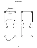
11) Installing the equalizing cables: refer to Fig 5 (pg. 25) for general cable arrangement for the
HD2P-15000C. Set carriages on the first safety latch engagement. Be sure each carriage
is at the same height by measuring from the top of the base to the bottom of the
carriage (double check the latches before working under the carriages). This dimension
should be within 1/4”. Run first cable Fig 5. Tighten nut on one cable stud so that the end
of stud passes the nylon on the nut. Pull the other end of cable and run nut on it. Tighten
both nuts. Repeat above for second cable.
12) Connect the hydraulic hoses, as shown on Fig. 6 (pg. 26) for HD2P-15000C Clear Floor
Type.
13) Mount the power unit on lift as shown in Fig. 6 (pg. 26).
14) Install the swing arms on the carriages using the included 1 1/2” diameter pins. Check
for proper engagement of the arm lock- the rack on the lock should fully engage the gear
on the arm.
15) Adjust the carriage cables tension. Adjust each cable to approximately 1/2” side-to-side
play. Check the latch releases to insure the carriage is still sitting on the appropriate
latch.
NOTE: Tightening cable adjustment nut on main side column will raise carriage
on offside column and vise versa. Refer to Fig 5 pg. 25.
16) Remove the fill cap from the power unit and fill the oil tank reservoir. To fill the oil tank
resevoir, the lift must be completely lowered. FIll the oil tank with a premium quality ISO-
32, or AW-46 Hydraulic Oil.
17) Make the Electrical hookup to the power unit.(220V Single Phase). It is recommended
that a 220 Volt, 30 Amp twist lock plug be installed in the power line just ahead of the
power unit. Use properly sized wire for 30-amp circuit.
WARNING: THE WIRING MUST COMPLY WITH LOCAL CODE. HAVE A
CERTIFIED ELECTRICIAN MAKE THE ELECTRICAL HOOK-UP TO THE POWER
UNIT. PROTECT EACH CIRCUIT WITH TIME DELAY FUSE OR CIRCUIT BREAKER;
208V-230V SINGLE PHASE. 60 HZ 30 AMP.
Summary of Contents for HD2P-15000C
Page 25: ...21 FIG 2 ARM SWING 148 3 8 Min 5 Max 7 4 3 4 3 34 1 2 R37 1 8 52 1 8 R37 1 8 52 1 8...
Page 26: ...22 FIG 3 COLUMN OVERVIEW...
Page 27: ...23 FIG 4 CABLES Locking Nuts 4 Bottom Cable Sheave Equalizing Cable 2 Top Cable Sheave...
Page 36: ......
Page 37: ...NOTES...
Page 38: ...NOTES...
Page 39: ...NOTES...


