


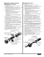


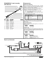
Repacking the Fluid Section
1. Remove the foot valve
assembly and the lower
housing using the steps in the
“Servicing the Valves”
procedure above.
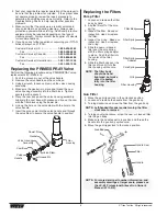
2. Slide the retaining ring up on
the slider assembly to expose
the connecting pin.
3. Push the connecting pin
forward through the slider
assembly and piston. The
connecting pin will fall into a
recessed area of the gear box
housing where it can be
retrieved.
4. Tap the knock-off nut with a
soft hammer so that it turns
counterclockwise and loosens.
5. Turn the fluid section
counterclockwise to remove it
from the gear box housing.
6. Place the upper housing
upright in a vise by clamping
on the wrench flats.
7. Using a wrench, remove the
upper seal retainer.
8. Slide the piston rod out through
the bottom of the upper
housing.
9. Inspect the piston rod for wear
and replace if necessary.
10. Remove the upper and lower packings from the upper
housing.
11. Clean the upper housing. Inspect the upper housing for
damage and replace if necessary.
12. Locate the new upper and lower packings and pack the
areas between the packing lips with grease. Lubricate the
o-rings on the exterior of the packings with grease.
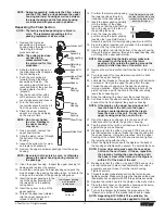
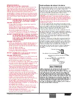
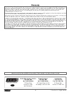
13. Insert the upper packing into the
top of the upper housing with
the raised lip on the packing
facing down.
14. Insert the spacer on top of the
upper packing.
15. Thread the upper seal retainer
into the upper housing and
torque to 25-30 ft. lbs.
Install upper packing
with raised lip
facing down.
Raised Lip
NOTE: Be careful not to scratch, score, or otherwise
damage the upper housing during removal of
the packings.
NOTE: Do not over-tighen
the vise. Damage to
the upper housing
may occur.
NOTE: The outlet valve does
not need to be
disassembled from
the piston rod for this
procedure.
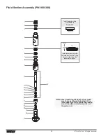
Retaining
Ring
Connecting
Pin
Slider
Assembly
Crankshaft
Knock-Off
Nut
Upper Seal
Retainer
Spacer
Upper
Packing
Lower
Packing
Upper
Housing
Piston Rod
Wear Ring
NOTE: The factory-installed packings are black in
color. The replacement packings in the
packing replacement kit are white.
NOTE: During reassembly, make sure the Viton o-rings
and the
PTFE
back-up rings between the upper
housing and lower housing as well as between
the lower housing and the foot valve housing
are lubricated with grease and in position.
16. Pre-form the lower packing using
the lower packing sizing tool
(included in the repacking kit).
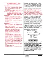
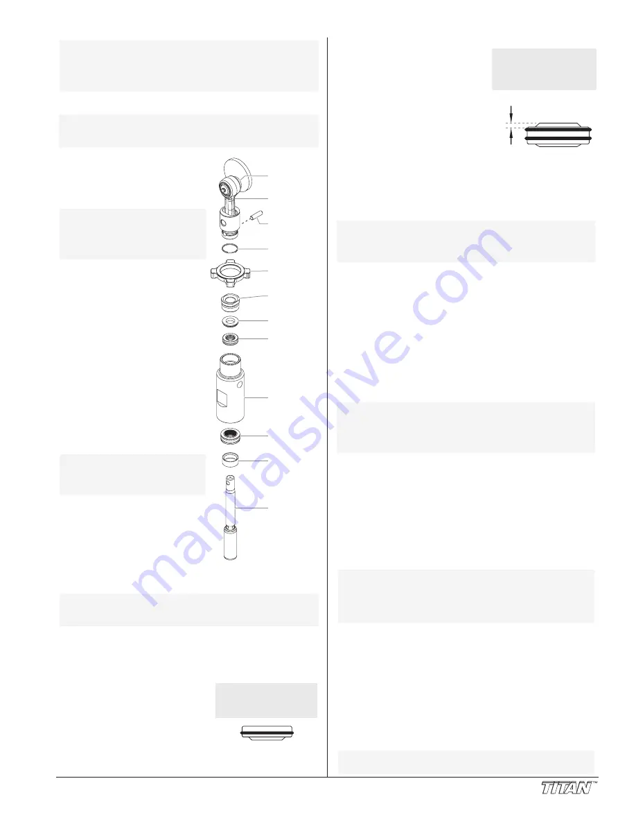
17. Insert the lower packing partially
into the bottom of the upper
housing so that the side that has
the o-ring closest to the face of
the packing faces up.
18. Push the lower packing into
position using the lower packing
insertion tool (see Fluid Section
Assembly parts list for lower packing insertion tool P/N).
19. Place the piston insertion tool (included in the repacking
kit) over the top of the piston rod.
20. Insert the piston rod into the bottom of the upper housing,
through the lower packing, through the upper packing, and
out through the upper seal retainer.
21. Remove the piston insertion tool from the top of the piston
rod.
22. Turn the knock-off nut counterclockwise until it is flush
against the upper housing.
23. Lubricate the threads on the upper housing with anti-seize
compound. Remove the upper housing from the vise.
24. Thread the upper housing into the gear box housing,
turning clockwise. When the connecting pin hole on the
piston rod lines up with the hole in the slider assembly,
insert the connecting pin.
25. Slide the retaining ring down over the connecting pin.
26. Continue to turn the upper housing clockwise until the
knock-off nut is flush against the gear box housing.
27. Once the nipple is positioned, turn the knock-off nut
clockwise until it contacts the gear box housing.
28. Tap the knock-off nut with a soft hammer to tighten it
against the gear box housing.
29. Making sure that the Viton o-ring and
PTFE
back-up ring
are lubricated and in place, thread the lower housing into
the upper housing. Using two wrenches, hold the upper
housing at the wrench flats with one wrench and tighten
the lower housing with the other.
30. Attach the high-pressure hose to the nipple on the back of
the housing and tighten with a wrench. Do not kink the hose.
31. Making sure that the Viton o-ring and
PTFE
back-up ring
are lubricated and in place, reassemble the foot valve
assembly and and thread it into the lower housing.
Tighten securely.
32. Thread the siphon tube/siphon set into the foot valve and
tighten securely. Make sure to wrap the threads on the down
tube/siphon hose adapter with
PTFE
tape before assembly.
33. Replace the return hose into the clamp on the siphon tube.
34. Place the front cover on the gearbox housing and secure
in position using the four front cover screws.
35. Turn on the sprayer by following the procedure in the
“Operation” section of this manual and check for leaks.
NOTE: Repacking kit P/N 800-273 is available. For
best results use all parts supplied in this kit.
NOTE: For low rider units, make sure the hose does
not touch the cart frame. If it does, reposition
the nipple by turning the upper housing until
the hose is clear of the frame and the nipple is
within 45º of the back of the unit.
NOTE: If the nipple on the upper housing does not
face the back of the unit, turn the upper
housing counterclockwise until the nipple
faces the back of the unit. Do not turn the
upper housing more than one full turn.
NOTE: When repacking the fluid section, make sure
the raised lip on the bottom of the lower
packing is fully outside the packing around the
piston rod after insertion of the piston rod.
Install lower packing with
the side that has the o-ring
closest to the face of the
packing facing up.
Closer
Top
© Titan Tool Inc. All rights reserved.
11


