

© Titan Tool Inc. All rights reserved.
21
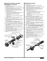
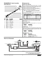
Item
Part #
Description
Quantity
1
800-325
Upper seal retainer .....................................1
2
800-327
Spacer ........................................................1
3
800-248
Upper packing assembly ............................1
4
800-351
Upper housing ............................................1
5
800-250
Lower packing assembly ............................1
6
800-354
Wear ring ....................................................1
7
800-332
O-ring, Viton................................................2
8
800-333
Back-up ring,
PTFE
....................................2
9
800-352
Lower housing ............................................1
10
800-246
Piston rod....................................................1
11
800-348
Outlet valve seal .........................................1
12
800-244
Outlet valve cage........................................1
13
800-247
Outlet valve ball ..........................................1
Item
Part #
Description
Quantity
14
800-245
Washer, nylon .............................................1
15
800-243
Outlet valve seat.........................................1
16
800-336
Outlet valve retainer ...................................1
17
800-322
Foot valve cage ..........................................1
18
800-242
Foot valve ball ............................................1
19
800-241
Foot valve seat ...........................................1
20
762-058
O-ring..........................................................1
21
800-305
Foot valve housing .....................................1
22
800-365
Piston assembly (includes items 10–16) ....1
800-359
Lower packing insertion tool
800-273
Repacking kit (includes items 2, 3, 5–8, 11,
13, 14, 18, 20, and tool)
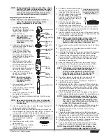
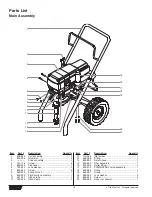
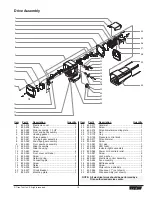
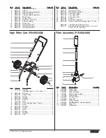
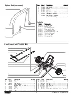
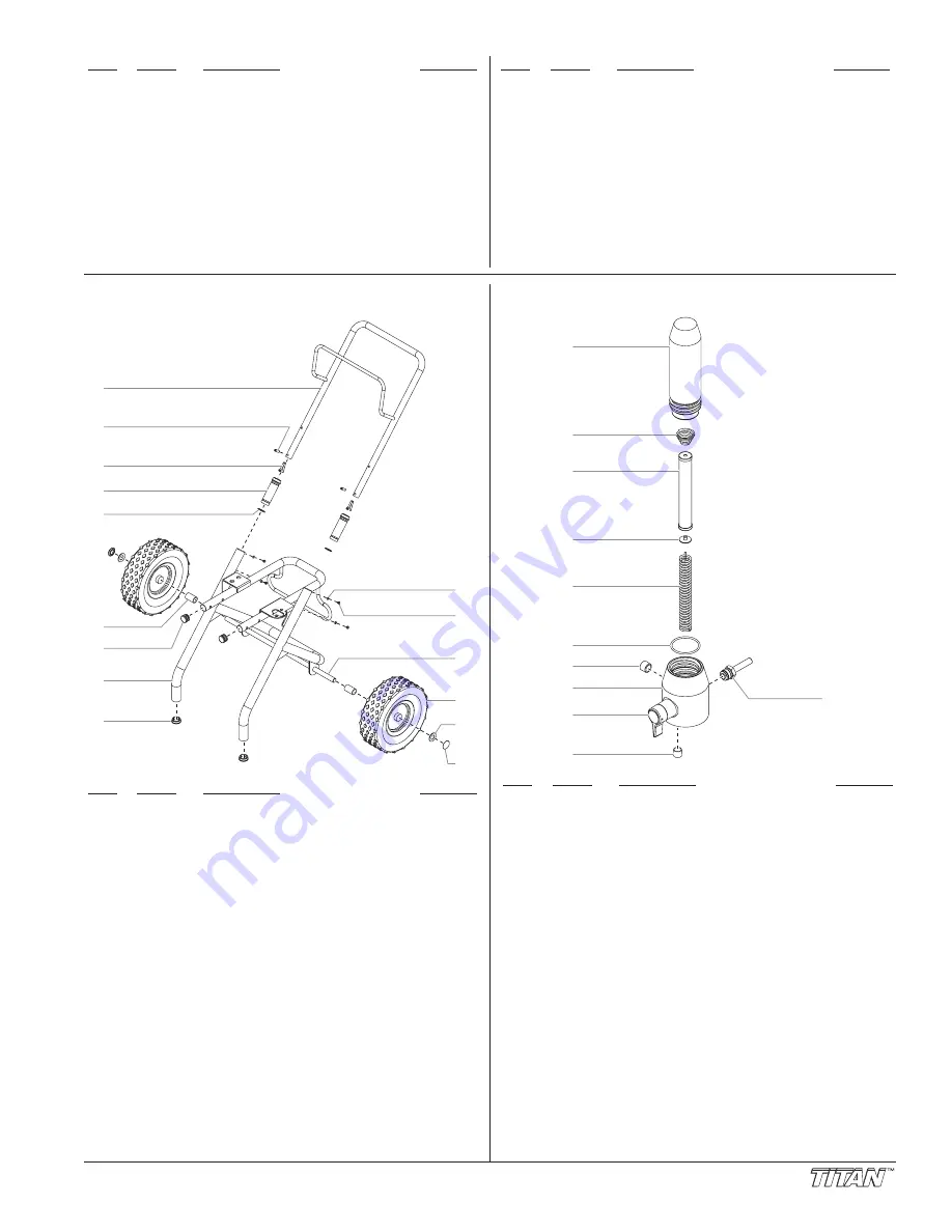
High Rider Cart (P/N 800-600)
Item
Part #
Description
Quantity
1
800-280
Handle
(includes items 2–5, 10, and 11) ................1
2
590-508
Roll pin........................................................2
3
590-507
Snap button ................................................2
4
590-504
Sleeve.........................................................2
5
590-506
Washer........................................................2
6
800-011
Spacer ........................................................2
7
710-199
Plug.............................................................2
8
800-279
Cart (includes items 7 and 9) .....................1
9
335-018
Plug.............................................................2
10
856-002
Washer........................................................4
11
856-921
Screw..........................................................4
12
800-007
Axle.............................................................1
13
670-109
Wheel..........................................................2
14
870-004
Washer........................................................2
15
800-019
Cap .............................................................2
1
3
4
2
5
6
7
9
8
10
11
12
14
15
13
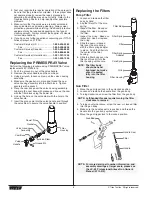
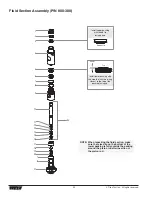
Filter Assembly (P/N 800-900)
Item
Part #
Description
Quantity
1
800-905
Filter body ...................................................1
2
800-252
Filter spring .................................................1
3
730-067
Filter, 60 mesh ............................................1
4
702-251
Filter spring adapter....................................1
5
757-105
Core spring .................................................1
6
800-906
O-ring,
PTFE
..............................................1
7
800-908
Plug, 3/8” ....................................................1
8
800-901
Filter housing ..............................................1
9
800-915
PRIME/SPRAY valve assembly..................1
10
800-907
Plug, 1/4” ....................................................1
11
800-437
Transducer..................................................1
6
7
8
9
10
2
1
3
4
5
11


