


Solid Yellow
When the pressure indicator is solid yellow, the sprayer is
operating between 200 and 1800 PSI. A solid yellow pressure
indicator means:
• The sprayer is at the proper pressure setting for spraying
stain, lacquer, varnish, and multi-colors.
• If the pressure indicator goes to solid yellow when the
pressure is set so that it starts at solid green, it indicates
one of the following:
a. Tip Wear Indicator — when spraying with latex or at
high pressure the solid yellow appears. This means
the tip is worn and needs to be replaced.
b. Tip Too Large — when a tip that is too large for the
sprayer is put in the gun, the pressure indicator will turn
from solid green to solid yellow.
c. Fluid Section Wear — if a solid yellow pressure
indicator appears when using a new tip and the
pressure is set at maximum, service may be required
(worn packings, worn piston, stuck valve, etc...).
Solid Green
When the pressure indicator is solid green, the sprayer is
operating between 1800 and 3300 PSI. A solid green pressure
indicator means:
• The sprayer is at the proper pressure setting for spraying
oil-based and latex house paints.
• The sprayer is operating at peak performance at a high
pressure setting.
Motor Running Indicator
The Motor Running indicator is on when the motor is
commanded to run. This indicator is used by service centers
to troubleshoot motor problems.
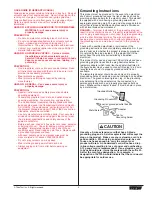
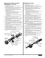
Pressure Relief Procedure
Be sure to follow the pressure relief procedure when
shutting the unit down for any purpose, including
servicing or adjusting any part of the spray system,
changing or cleaning spray tips, or preparing for cleanup.
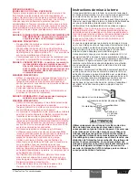
1. Lock the gun by turning the gun trigger
lock to the locked position.
2. Turn the pressure control knob
counterclockwise to its OFF position in
the black zone.
3. Unlock the gun by turning the gun
trigger lock to the unlocked position.
4. Hold the metal part of the gun firmly to
the side of a metal container to ground
the gun and avoid a build up of static
electricity.
5. Trigger the gun to remove any pressure
that may still be in the hose.
6. Lock the gun by turning the gun trigger lock to the locked
position.
7. Move the PRIME/SPRAY valve down to the PRIME
position.
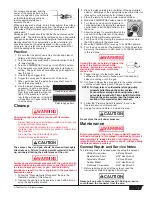
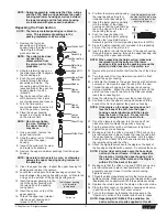
Spraying
POSSIBLE INJECTION HAZARD. Do not spray without the
tip guard in place. Never trigger the gun unless the tip is
in either the spray or the unclog position. Always engage
the gun trigger lock before removing, replacing, or
cleaning tip.
WARNING
Trigger lock
in locked position.
WARNING
6
© Titan Tool Inc. All rights reserved.
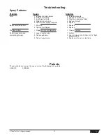
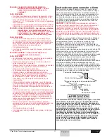
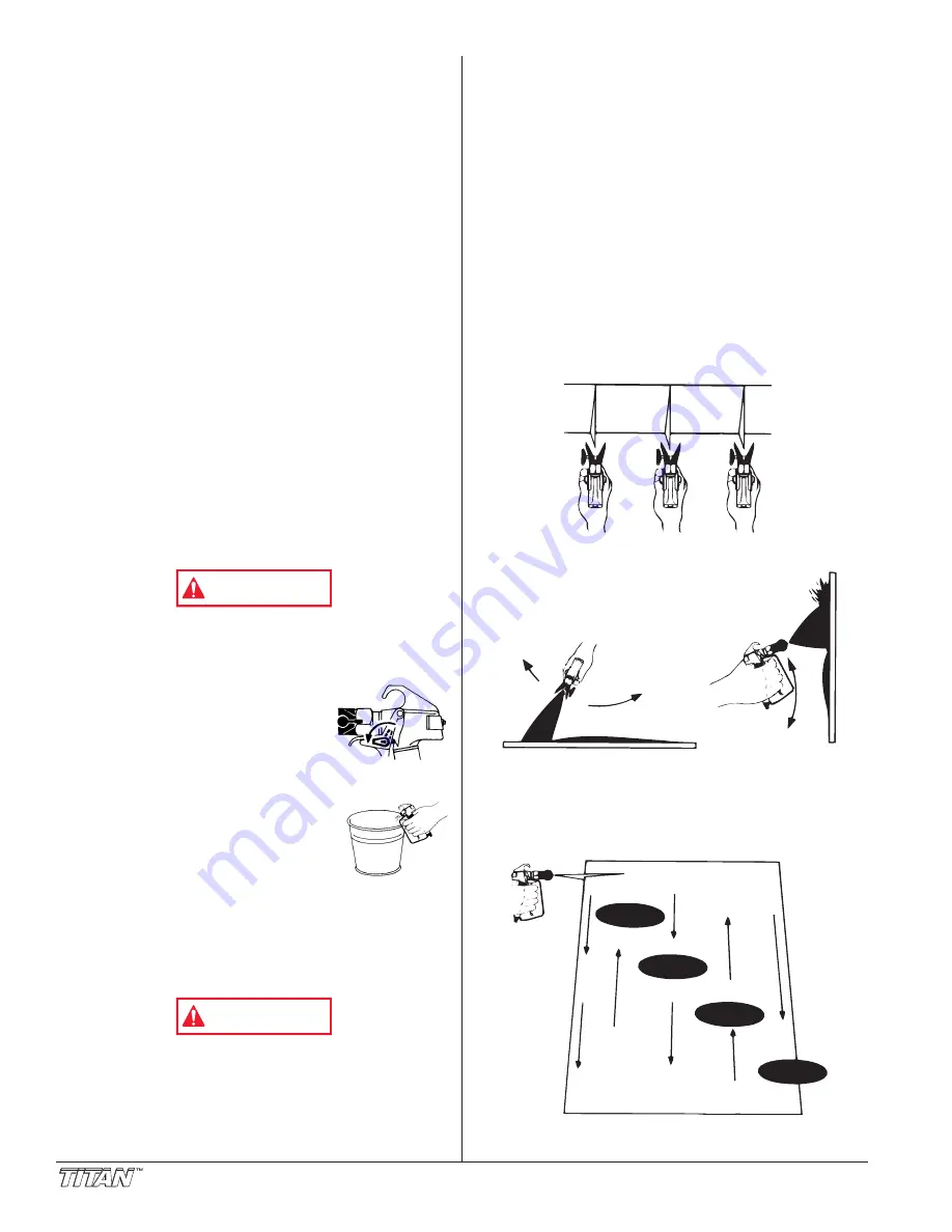
Spraying Technique
The following techniques, if followed, will assure professional
painting results.
Hold the gun perpendicular to the surface and always at equal
distance from the surface. Depending on the type of material,
surface, or desired spray pattern, the gun should be held at a
distance of 12 to 14 inches (30 to 35 cm).
Move the gun either across or up and down the surface at a
steady rate. Moving the gun at a consistent speed conserves
material and provides even coverage. The correct spraying speed
allows a full, wet coat of paint to be applied without runs or sags.
Holding the gun closer to the surface deposits more paint on
the surface and produces a narrower spray pattern. Holding
the gun farther from the surface produces a thinner coat and
wider spray pattern. If runs, sags, or excessive paint occur,
change to a spray tip with a smaller orifice. If there is an
insufficient amount of paint on the surface or you desire to
spray faster, a larger orifice tip should be selected.
Maintain uniform spray stroke action. Spray alternately from
left to right and right to left. Begin movement of the gun before
the trigger is pulled.
Avoid arcing or holding the gun at an angle. This will result in
an uneven finish.
Proper lapping (overlap of spray pattern) is essential to an
even finish. Lap each stroke. If you are spraying horizontally,
aim at the bottom edge of the preceding stroke, so as to lap
the previous pattern by 50%.
Overlap edges
1st
pass
2nd
pass
3rd
pass
4th
pass
5th
pass
Too Thick
Offspray
Arcing
Gun at angle
start
stroke
release
trigger
pull
trigger
end
stroke


