background image

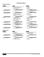
2. Test your repair before regular operation of the sprayer to

be sure that the problem is corrected.  If the sprayer does
not operate properly, review the repair procedure to
determine if everything was done correctly.  Refer to the
Troubleshooting Charts to help identify other possible
problems.

3. Make certain that the service area is well ventilated in

case solvents are used during cleaning.  Always wear
protective eyewear while servicing.  Additional protective
equipment may be required depending on the type of
cleaning solvent.  Always contact the supplier of solvents
for recommendations.

4. If you have any further questions concerning your TITAN

Airless Sprayer, call TITAN:

Customer Service (U.S.) .......................

1-800-526-5362

Fax ................................................

1-800-528-4826

Customer Service (Canada) ..................

1-800-565-8665

Fax ................................................

1-905-856-8496

Customer Service (International)...........

1-201-337-1240

Fax ................................................

1-201-405-7449

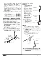
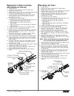
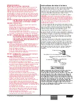
Replacing the PRIME/SPRAY Valve

Perform the following procedure using PRIME/SPRAY valve
replacement kit P/N 800-915.

1. Push the groove pin out of the valve handle.
2. Remove the valve handle and the cam base.
3. Using a wrench, loosen and remove the valve housing

assembly.

4. Make sure the gasket is in place and thread the new

valve housing assembly into the filter block.  Tighten
securely with a wrench.

5. Place the cam base over the valve housing assembly.

Lubricate the cam base with grease and line up the cam
with the filter block using the dowel pin.

6. Line up the hole on the valve stem with the hole in the

valve handle. 

7. Insert the groove pin into the valve handle and through

the valve stem to secure the valve handle in position.

Gasket

Dowel Pin

Cam Base

Valve Stem

Filter 

Housing

Valve Housing 

Assembly

Valve 

Handle 

Groove Pin

8

© Titan Tool Inc.  All rights reserved.

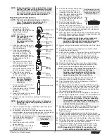
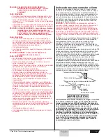
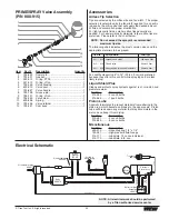
Replacing the Filters 

Pump Filter

1. Loosen and remove the filter

body by hand.

2. Slip the filter off of the core

spring.

3. Inspect the filter.  Based on

inspection, clean or replace
the filter.

4. Inspect the o-ring.  Based on

inspection, clean or replace
the o-ring.

5. Slide the new or cleaned

filter over the core spring
with the filter spring adapter
in place.  Push the filter into
the center of the filter
housing.

6. Slide the filter body over the

filter and thread it into the
filter housing until secure.
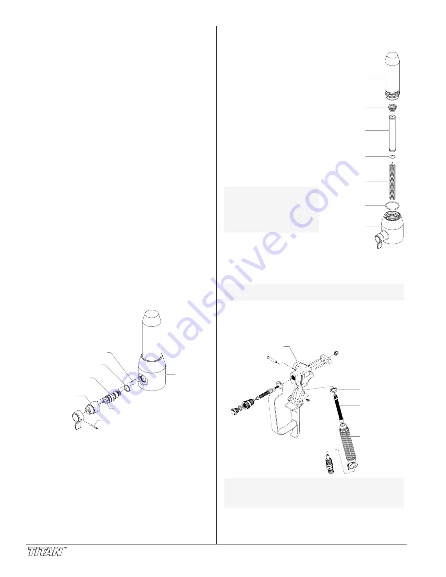
Gun Filter

1. Move the gun trigger lock to the unlocked position.
2. Loosen and remove the handle from the gun body.
3. Turning clockwise, unscrew the filter from the gun body. 

4. Turning counterclockwise, screw the new or cleaned filter

into the gun body.

5. Make sure the handle seal is in position and thread the

handle into the gun body until secure.

6. Move the gun trigger lock to the locked position.

NOTE: For more detail, part number information, and

assembly drawings at larger scale, please see
the LX -80 Professional Airless Gun Owner's
Manual (#313-012).

Gun Body

Handle Seal

Filter

Handle

NOTE: Left-handed threads require turning the filter

clockwise to remove.

NOTE: The filter body

should be hand-
tightened, but make
sure it is seated
fully into the filter
housing.

Filter Body

Filter Spring

Filter Spring 

Adapter

Core Spring

Filter

O-ring

Filter Housing

Summary of Contents for 1140ix

Page 1: ...yer Owner s Manual For professional use only NOTE This manual contains important warnings and instructions Please read and retain for reference NOTE This manual contains important warnings and instruc...

Page 2: ...Refer to the PRESSURE RELIEF PRESSURE described in the pump manual ALWAYS keep tip guard in place while spraying The tip guard provides some protection but is mainly a warning device ALWAYS remove th...

Page 3: ...uct must be grounded In the event of an electrical short circuit grounding reduces the risk of electric shock by providing an escape wire for the electric current This product is equipped with a cord...

Page 4: ...ned out of the system with mineral spirits before you begin spraying Always keep the trigger lock on the spray gun in the locked position while preparing the system 1 Place the siphon tube into a cont...

Page 5: ...he gun into the metal waste container until all air and solvent is flushed from the spray hose and paint is flowing freely from the gun WARNING On Off Clean Min PSI Bar Max PSI Bar S p r a y L a t e x...

Page 6: ...up of static electricity 5 Trigger the gun to remove any pressure that may still be in the hose 6 Lock the gun by turning the gun trigger lock to the locked position 7 Move the PRIME SPRAY valve down...

Page 7: ...olvent WARNING CAUTION WARNING Good spray pattern Paint tailing pattern Titan Tool Inc All rights reserved 7 3 Place the siphon tube into a container of the appropriate solvent Examples of the appropr...

Page 8: ...stem with the hole in the valve handle 7 Insert the groove pin into the valve handle and through the valve stem to secure the valve handle in position Gasket Dowel Pin Cam Base Valve Stem Filter Housi...

Page 9: ...the four motor shroud screws Remove the motor shroud 3 Release the tie wrap on the top of the baffle assembly and slip the baffle assembly down off of the motor 4 Loosen and remove the three electroni...

Page 10: ...rn off and unplug the unit Before proceeding follow the Pressure Relief Procedure outlined previously in this manual Additionally follow all other warnings to reduce the risk of an injection injury in...

Page 11: ...ng kit over the top of the piston rod 20 Insert the piston rod into the bottom of the upper housing through the lower packing through the upper packing and out through the upper seal retainer 21 Remov...

Page 12: ...er tripped 1 Air in line 2 Insufficient pressure 1 No paint 2 Siphon strainer clogged 3 Sprayer gun filter clogged 4 Sprayer will not prime material too heavy 1 Air leak in system 2 Air leak in siphon...

Page 13: ...ayer capacity 1 Worn tip 2 Tip may be chipped 1 Plugged worn or chipped tip 1 Leak in suction tube 2 Not enough hose 3 Tip too large or worn Solution 1 Increase pressure 2 Change to smaller tip 3 Clea...

Page 14: ...ntion particuli re ATTENTION AVERTISSEMENT DANGER RISQUES D EXPLOSION OU D INCENDIE Les vapeurs d gag es par le solvant ou la peinture sont explosives et inflammables et peuvent causer des corporels s...

Page 15: ...t Ne jamais r parer un flexible d alimentation en peinture Le remplacer par un autre flexible mis la terre Tout flexible raccord orientable pistolet et accessoire utilis avec cet appareil doit pouvoir...

Page 16: ...PARA PREVENIR Debe proveerse un escape y aire fresco para hacer que el aire que est dentro del rea de atomizaci n se mantenga libre de acumulaciones de vapores inflamables Evite todas las fuentes de i...

Page 17: ...ierra reduce el riesgo de choque el ctrico al proporcionar un alambre de escape para la corriente el ctrica Este producto est equipado con un cable que tiene un alambre de conexi n a tierra con un enc...

Page 18: ...551 Lock washer 2 7 858 625 Screw 2 8 800 328 Knock off nut 1 9 800 300 Fluid section assembly 1 10 451 241 Siphon tube 1 11 730 334 Hose clamp 1 Item Part Description Quantity 12 710 046 Inlet screen...

Page 19: ...753 Connecting pin 1 17 800 202 Screw 2 18 800 276 Relay 1 19 704 229 Screw 1 20 765 327 Circuit breaker 1 21 800 075 Mounting plate 1 Item Part Description Quantity 22 800 077 Grommet 1 23 800 076 S...

Page 20: ...packing with the side that has the o ring closest to the top of the packing facing up Install upper packing with raised lip facing down Raised Lip 22 Closer Top NOTE When repacking the fluid section...

Page 21: ...des items 10 16 1 800 359 Lower packing insertion tool 800 273 Repacking kit includes items 2 3 5 8 11 13 14 18 20 and tool High Rider Cart P N 800 600 Item Part Description Quantity 1 800 280 Handle...

Page 22: ...ess to Reset label 313 1848 Pressure control knob label 313 1867 Indicator lights label 313 1652 Titan front label 313 1906 Infinity logo label Low Rider Cart P N 800 590 1 2 3 4 5 6 7 8 9 10 11 12 13...

Page 23: ...likely to plug Liquid Shield Plus Cleans and protects spray systems against rust corrosion and premature wear Part No Description 314 483 4 ounce bottle 314 482 1 quart bottle Piston Lube Specially fo...

Page 24: ...on substitution of non Titan component parts or tampering with the unit in a manner to impair normal operation Defective parts are to be returned to an authorized Titan sales service outlet All transp...

Reviews: