


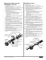


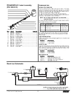
Replacing the Motor Assembly
(with Electronic Control)
1. Unplug the unit.
2. Loosen and remove the four motor shroud screws.
Remove the motor shroud.
3. Release the tie wrap on the top of the baffle assembly and
slip the baffle assembly down off of the motor.
4. Loosen and remove the three electronic cover screws.
Lift the electronic cover off of the electronic control
assembly on the motor.
5. At the electronic control assemly:
a. Disconnect the white wire coming from the power cord
and the white wire coming from the relay.
b. Disconnect the three wires coming from the
potentiometer.
c. Disconnect the seven wires coming from the indicator
lights assembly.
6. Loosen and remove the three motor mounting screws.
7. Pull the motor out of the gearbox housing.
8. With the motor removed, inspect the gears in the gearbox
housing for damage or excessive wear. Replace the
gears, if necessary.
9. Install the new motor into the gearbox housing. Make
sure the housing gasket is positioned properly.
10. Secure the motor with the three motor mounting screws.
11. Reconnect the wires to the electronic control assembly
(refer to the electrical schematic in the Parts List section
of this manual).
12. Position the electronic cover over the electronic control
assembly. Secure the electronic cover with the three
electronic cover screws.
13. Slip the baffle assembly up and around the motor. Secure
the baffle assembly with the tie wrap.
14. Slide the motor shroud over the motor. Make sure the
shroud gasked is positioned properly.
15. Secure the motor shroud with the four motor shroud
screws.
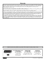
Electronic Cover
Motor Shroud
Motor Shroud Screws
Motor
Baffle Assembly
Housing Gasket
Shroud Gasket
Electronic Control
Assembly
Motor Mounting
Screw
Electronic Cover
Screw
Gearbox
Housing
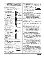
Replacing the Gears
1. Unplug the unit.
2. Loosen and remove the four motor shroud screws.
Remove the motor shroud.
3. Release the tie wrap on the top of the baffle assembly and
slip the baffle assembly down off of the motor.
4. Loosen and remove the three electronic cover screws.
Lift the electronic cover off of the electronic control
assembly on the motor.
5. At the electronic control assemly:
a. Disconnect the white wire coming from the power cord
and the white wire coming from the relay.
b. Disconnect the three wires coming from the
potentiometer.
c. Disconnect the seven wires coming from the indicator
lights assembly.
6. Loosen and remove the three motor mounting screws.
7. Pull the motor out of the gearbox housing.
8. Inspect the armature gear on the end of the motor for
damage or excessive wear. If this gear is completely
worn out, replace the front end bell assembly.
9. Remove and inspect the 1st stage gear and 2nd stage
gear assemblies for damage or excessive wear. Replace,
if necessary.
10. Remove and inspect the front gear box assembly for
damage or excessive wear. If damaged or worn, replace
the front gear box assembly.
11. Install the motor into the gearbox housing. Make sure the
housing gasket is positioned properly.
12. Secure the motor with the three motor mounting screws.
13. Reconnect the wires to the electronic control assembly
(refer to the electrical schematic in the Parts List section
of this manual).
14. Position the electronic cover over the electronic control
assembly. Secure the electronic cover with the three
electronic cover screws.
15. Slip the baffle assembly up and around the motor. Secure
the baffle assembly with the tie wrap.
16. Slide the motor shroud over the motor. Make sure the
shroud gasked is positioned properly.
17. Secure the motor shroud with the four motor shroud
screws.
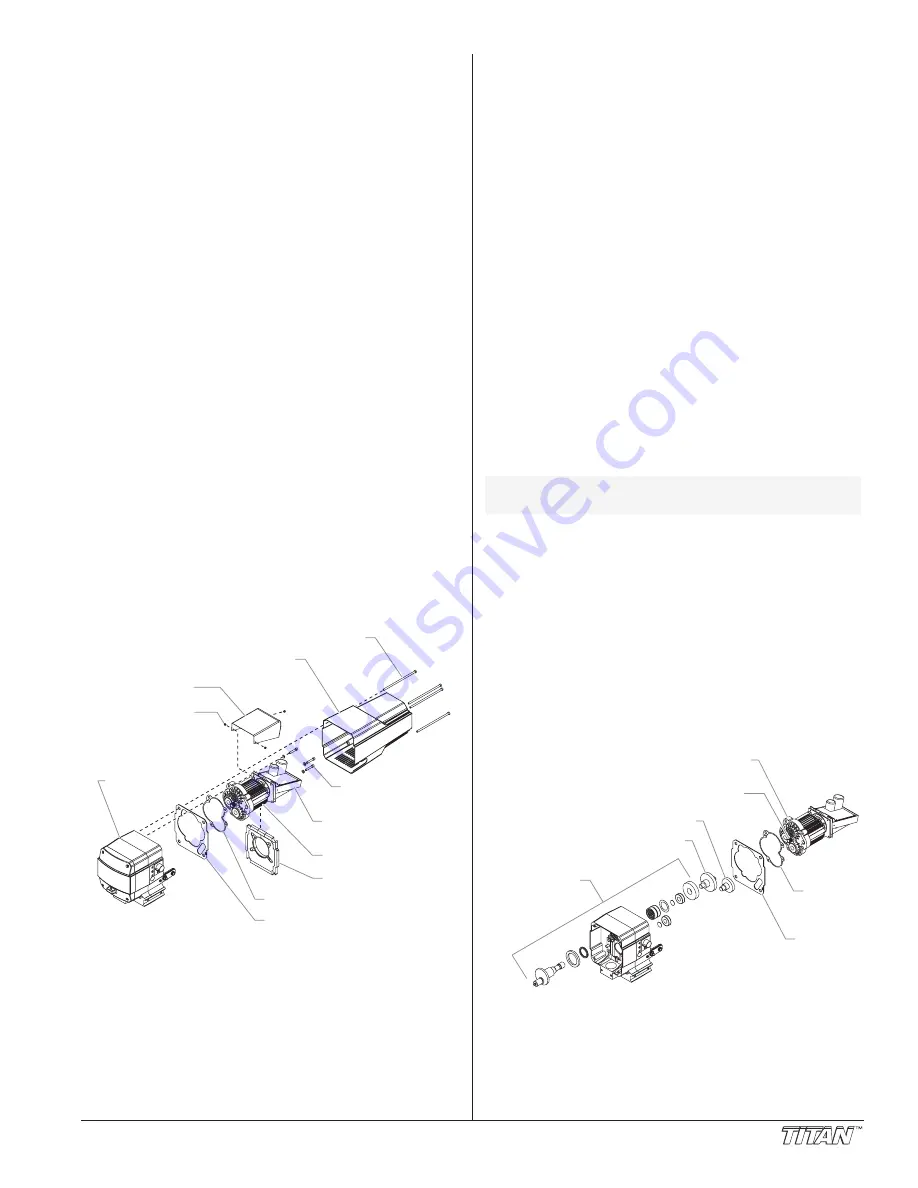
Front End Bell
Assembly
Armature Gear
1st Stage Gear
2nd Stage Gear
Front Gear Box
Assembly
Housing
Gasket
Shroud
Gasket
NOTE: Clean and refill the gear box cavity up to the rear
face of each gear with Lubriplate (P/N 314-171).
© Titan Tool Inc. All rights reserved.
9


