background image

English

English

© Titan Tool Inc.  All rights reserved. 

5

Preparing to Paint

Before painting, it is important to make sure that the fluid in the 

system is compatible with the paint that is going to be used.

  NOTE:  Incompatible fluids and paint may cause the valves 

to become stuck closed, which would require 

disassembly and cleaning of the sprayer’s fluid 

section.

ImPOrTaNT:  always keep the trigger lock on the spray gun in 

the locked position while preparing the system.
  1.  Place the siphon tube into a container of the appropriate 

solvent.  Examples of the appropriate solvent are water for 

latex paint or mineral spirits for oil-based paints.

RAPID

CLEAN

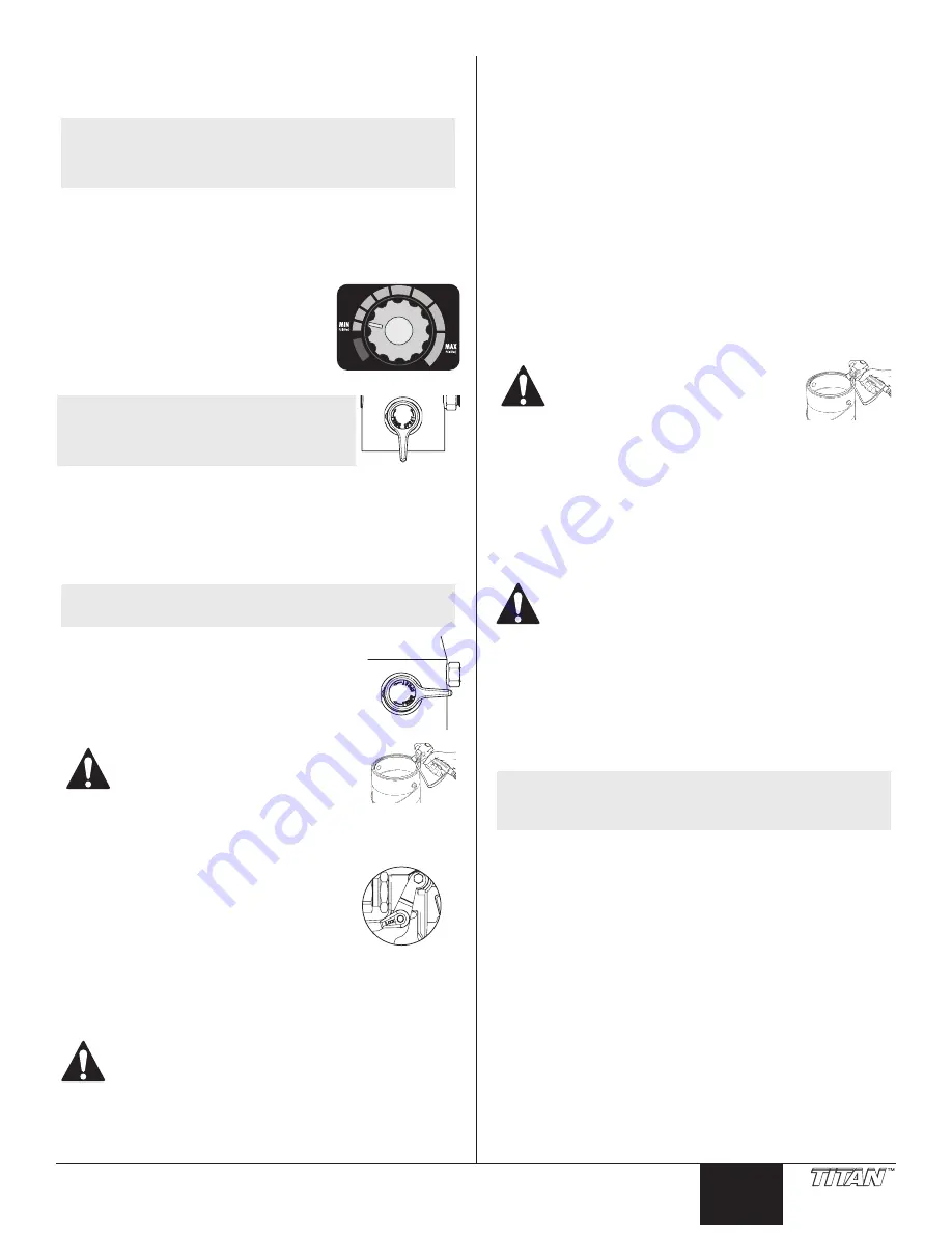
  2.  Place the return hose into a metal waste 

container.

  3.  Set the pressure to minimum by turning 

the pressure control knob to the “MIN” 

setting.

  4.  Move the PRIME/SPRAY valve down to 

the PRIME position.

  NOTE:  Hold the return hose in the waste 

container when moving the PrImE/

SPray valve to PrImE in case the 

sprayer is pressurized.

  5.  Turn on the sprayer by moving the ON/OFF switch to the ON 

position. 

  6.  Allow the sprayer to run for 15–30 seconds to flush the old 

solvent out through the return hose and into the metal waste 

container.

  7.  Turn off the sprayer by moving the ON/OFF switch to the OFF 

position.

  NOTE:  make sure that the spray gun does not have a tip or 

tip guard installed.

  8.  Move the PRIME/SPRAY valve up to the SPRAY 

position.

  9.  Turn on the sprayer.
  10.  Unlock the gun by turning the gun trigger 

lock to the unlocked position.

Ground the gun by holding it against 

the edge of the metal container while 

flushing.  Failure to do so may lead to 

a static electric discharge, which may 

cause a fire.


  11.  Trigger the gun into the metal waste container until the old 

solvent is gone and fresh solvent is coming out of the gun.

Trigger lock in 

locked position.

  12.  Lock the gun by turning the gun trigger 

lock to the locked position.

  13.  Set down the gun and increase the 

pressure by turning the pressure control 

knob slowly clockwise.

  14.  Check the entire system for leaks.  If 

leaks occur, follow the “Pressure Relief 

Procedure” in this manual before 

tightening any fittings or hoses.

  15.  Follow the “Pressure Relief Procedure” in this manual before 

changing from solvent to paint.

Be sure to follow the pressure relief procedure when 

shutting down the sprayer for any purpose, including 

servicing or adjusting any part of the spray system, 

changing or cleaning spray tips, or preparing for 

cleanup.

Painting

  1.  Place the siphon tube into a container of paint.
  2.  Place the return hose into a metal waste container.
  3.  Set the pressure to minimum by turning the pressure control 

knob to the “MIN” setting.

  4.  Move the PRIME/SPRAY valve down to the PRIME position.
  5.  Turn on the sprayer by moving the ON/OFF switch to the ON 

position.

  6.  Allow the sprayer to run until paint is coming through the 

return hose into the metal waste container.

  7.  Turn off the sprayer by moving the ON/OFF switch to the OFF 

position.

  8.  Remove the return hose from the waste container and place it 

in its operating position above the container of paint.

  9.  Move the PRIME/SPRAY valve up to the SPRAY position.
  10.  Turn on the sprayer.
  11.  Unlock the gun by turning the gun trigger lock to the 

unlocked position.

Ground the gun by holding it against 

the edge of the metal container while 

flushing.  Failure to do so may lead to 

a static electric discharge, which may 

cause a fire.


  12.  Trigger the gun into the metal waste container until all air and 

solvent is flushed from the spray hose and paint is flowing 

freely from the gun.

  13.  Lock the gun by turning the gun trigger lock to the locked 

position.

  14.  Turn off the sprayer.
  15.  Attach tip guard and tip to the gun as instructed by the tip 

guard or tip manuals.

POSSIBLE INjEcTION HaZarD.  Do not spray without 

the tip guard in place.  Never trigger the gun unless 

the tip is in either the spray or the unclog position.  

always engage the gun trigger lock before removing, 

replacing or cleaning tip.

  16.  Turn on the sprayer.
  17.  Increase the pressure by turning the pressure control knob 

slowly clockwise and test the spray pattern on a piece of 

cardboard.  Adjust the pressure control knob until the 

spray from the gun is completely atomized.  Try to keep the 

pressure control knob at the lowest setting that maintains 

good atomization.

  NOTE:  Turning the pressure up higher than needed to 

atomize the paint will cause premature tip wear and 

additional overspray.

Summary of Contents for IMPACT 840

Page 1: ...r reference Owner s Manual Notice d utilisation Manual del Propietario Do not use this equipment before reading this manual Model 805 009 Model 805 010 IMPACT 840 Airless Sprayer Anti Theft Digital Lo...

Page 2: ...ction systems are grounded to prevent static discharge Connect to a grounded outlet and use grounded extension cords electric models only Do not use a 3 to 2 adapter Do not use a paint or solvent cont...

Page 3: ...oing Do not operate the unit when fatigued or under the influence of drugs or alcohol Do not kink or over bend the hose Airless hose can develop leaks from wear kinking and abuse A leak can inject mat...

Page 4: ...e fill cap with a straight slot screwdriver or a coin Fill the oil reservoir with one ounce of piston seal lubricant Piston Lube Replace oiler cap 7 Press oiler button 2 5 times to prime the oiler Pre...

Page 5: ...ny fittings or hoses 15 Follow the Pressure Relief Procedure in this manual before changing from solvent to paint Be sure to follow the pressure relief procedure when shutting down the sprayer for any...

Page 6: ...g indicator is on when the motor is commanded to run This indicator is used by service centers to troubleshoot motor problems NOTE If the motor running and pressure indicators blink alternately it mea...

Page 7: ...ear and you will need to enter 1111 ENTER OLD CODE NUMBER XXXX Enter the old security code number to access the screen that allows the code change If the wrong code is entered the display will continu...

Page 8: ...an even finish Lap each stroke If you are spraying horizontally aim at the bottom edge of the preceding stroke so as to lap the previous pattern by 50 Overlap edges 1st pass 2nd pass 3rd pass 4th pas...

Page 9: ...e which may cause a fire 12 Trigger the gun into the metal waste container until the paint is flushed out of the hose and solvent is coming out of the gun 13 Continue to trigger the spray gun into the...

Page 10: ...nd remove the two 2 motor cover screws Remove the motor cover 5 Disconnect all wires between the motor and the sprayer 6 Loosen and remove the four 4 control panel screws Remove the control panel 7 Di...

Page 11: ...s Remove the motor shroud 4 Loosen and remove the two 2 motor cover screws Remove the motor cover 5 Disconnect the transducer wire from the motor controller 6 Pull the grommet out of the mounting plat...

Page 12: ...electric shock Always unplug the sprayer before servicing 7 Remove the return hose from the clamp on the siphon tube 8 Unscrew the siphon tube siphon set from the foot valve 9 Loosen and remove the h...

Page 13: ...piston rod 19 Insert the piston rod into the bottom of the upper housing through the lower packing through the upper packing and out through the upper seal retainer NOTE When repacking the fluid sect...

Page 14: ...ck the siphon tube siphon assembly connection and tighten or re tape the connection with PTFE tape 3 Remove the pump filter element and clean Remove the inlet screen and clean 4 Remove the siphon tube...

Page 15: ...air Check Potentiometer Screen CHECK POTENTIOMETER The Check Potentiometer screen appears when the potentiometer has become disconnected or is defective Take the sprayer to a Titan authorized service...

Page 16: ...3 2 N utilisez pas de peinture ou de solvant contenant du halon par exemple le chlore les agents antimoisissure l eau de Javel le chlorure de m thyl ne et le trichloro thane Ils ne sont pas compatible...

Page 17: ...eux pieds pour toujours conserver l quilibre Soyez attentif et regardez ce que vous faites N utilisez pas l appareil quand vous tes fatigu ou sous l influence de drogues ou d alcool Ne faites pas de n...

Page 18: ...l aide d un tournevis t te plate Remplir le r servoir avec une once de piston sceau lubrifiant Piston Lube Remplacer le bouchon de graisseur 7 Poussez 2 5 fois sur le bouton pour pr parer la graisseu...

Page 19: ...cords 15 Proc der aux tapes de la section Proc dure de d compression du pr sent manuel avant de passer du solvant au produit de peinture On doit effectuer la proc dure de d compression chaque fois qu...

Page 20: ...st mis en marche Cet indicateur est utilis par les centres techniques pour r parer les probl mes de moteur NOTA Les indicateurs de marche et de pression qui clignotent en alternance indiquent que le m...

Page 21: ...t le pulv risateur ne fonctionnera pas Pour programmer ou changer le code de s curit appuyer sur la touche no 2 NOTA Si le pulv risateur est neuf aucun code de s curit n est programm et l cran princip...

Page 22: ...irait un fini in gal Trop pais Vaporisation hors cible Mouvements semi circulaires Pistolet inclin Il est essentiel de faire chevaucher chacun des passages pour obtenir un fini uniforme Si par exemple...

Page 23: ...u ce que le solvant s coule du pistolet 13 Continuer d appuyer sur la d tente en direction du contenant m tallique jusqu ce que le solvant vacu soit propre NOTA Pour l entreposage long terme en milieu...

Page 24: ...moteur Retirez le carter 5 D branchez tous les fils reliant le moteur au pulv risateur 6 D vissez et retirez les quatre 4 vis du panneau de commandes Retirez le panneau de commandes 7 D branchez les f...

Page 25: ...D vissez et retirez les deux 2 vis du carter de moteur Retirez le carter du moteur 5 D branchez le c ble du transducteur du contr leur de moteur 6 Retirez l anneau isolant de la plaque d assemblage et...

Page 26: ...7 Retirez le tuyau de retour de la bride de serrage du tube siphon 8 D vissez le tube siphon jeu de siphons du clapet de pied 9 D vissez et retirez le tuyau haute pression du raccord derri re le loge...

Page 27: ...sup rieur le c t dont le joint torique est le plus pr s de la garniture vers le haut 17 Ins rez la garniture d tanch it inf rieure au moyen de l outil d insertion de la garniture d tanch it inf rieur...

Page 28: ...le raccord avec du ruban en PTFE 3 D monter le filtre de la pompe et le nettoyer D monter le filtre d entr e et le nettoyer 4 D monter le flexible du siphon d aspiration et le nettoyer 1 Remplacer l...

Page 29: ...p lev e Pour r paration apporter le pulv risateur un centre de service autoris Titan cran Charge m canique lev e High Mechanical Load HIGH MECHANICAL LOAD L cran Charge m canique lev e appara t lorsqu...

Page 30: ...rra especificadas por el fabricante Compruebe que todos los recipientes y sistemas de recogida est n conectados a tierra para evitar descargas el ctricas Conecte a una salida con toma a tierra y utili...

Page 31: ...a influencia del alcohol o de las drogas No retuerza ni doble la manguera en exceso En la manguera airless pueden aparecer fugas a causa del desgaste de retorcimientos o de un mal uso Una fuga puede i...

Page 32: ...Llene el lubricador con una oz de lubricante de sello de pist n Piston Lube Coloque la tapa 7 Presione el bot n e 2 5 veces para preparar el lubricador para lubricar la secci n de fluidos Presione una...

Page 33: ...presi n en este manual antes de apretar conectores o mangueras 15 Siga el Procedimiento para aliviar la presi n de este manual antes de cambiar de solvente a pintura No deje de seguir el procedimient...

Page 34: ...ha est encendido cuando el motor ha recibido la orden de ponerse en marcha Este indicador es utilizado por los centros de servicio para solucionar problemas de los motores NOTA Si el motor est en marc...

Page 35: ...es nuevo no hay c digo de seguridad configurado y aparecer la pantalla principal en el inicio Cuando se seleccione por primera vez un c digo de seguridad no aparecer la pantalla Enter Old Code Number...

Page 36: ...a solapando el patr n de rociado es algo indispensable para lograr un acabado parejo Superponga cada pasada Si roc a horizontalmente apunte al borde inferior de la pasada precedente de tal modo que se...

Page 37: ...pistola en el recipiente met lico para desecho hasta que se haya purgado toda la pintura de la manguera y est saliendo solvente de la pistola 13 Contin e apretando el gatillo de la pistola rociadora...

Page 38: ...la cubierta del motor 5 Desconecte todos los cables entre el motor y el pulverizador 6 Suelte y retire los cuatro 4 tornillos del panel de control Retire el panel de control 7 Desconecte los cables en...

Page 39: ...conjunto de filtro del carro 3 Suelte y retire los dos 2 tornillos de la carcasa del motor Retire la carcasa del motor 4 Suelte y retire los dos 2 tornillos de la cubierta del motor Retire la cubierta...

Page 40: ...te siempre el pulverizador antes de realizar mantenimiento 7 Retire la manguera de retorno de la abrazadera del tubo del sif n 8 Destornille el conjunto de tubo de sif n sif n de la v lvula de retenci...

Page 41: ...dura inferior consulte la lista de piezas del conjunto de la secci n de l quido para conocer el N P de la herramienta de inserci n de la empaquetadura inferior 18 Coloque la herramienta de inserci n d...

Page 42: ...ltro de bomba y l mpielo Quite la malla de entrada y l mpiela 4 Quite el tubo de sif n juego de succi n y l mpielo 1 Quite la punta rociadora siguiendo las instrucciones suministradas con la pistola r...

Page 43: ...dor a un servicio t cnico autorizado Titan para que lo reparen Pantalla High Mechanical Load HIGH MECHANICAL LOAD La pantalla High Mechanical Load Carga mec nica alta aparece cuando el pulverizador se...

Page 44: ...ts reserved Parts List Liste de pi ces Lista de piezas Main Assembly Vue d ensemble Ensamblaje principal 1 19 25 26 27 28 29 30 31 24 14 13 12 33 32 15 16 17 18 20 21 22 23 3 4 7 8 9 10 11 5 6 2 2 34...

Page 45: ...15A Fusible 15A 1 22 9804916 Fuse block screw Vis de bloc de fusible Tornillo de bloque de fusible 1 23 0522210 Fuse block Bloc de fusible Bloque de fusible 1 24 805 254A Face plate oiler assembly En...

Page 46: ...in engrenages Ensamblaje cig e al engranaje 1 5 805 240 1st stage gear Engrenage du 1er tage Engranajes de la primera etapa 1 6 805 265A Motor assembly Ensemble de moteur Ensamblaje del motor 1 7 700...

Page 47: ...is Description Espa ol Descripci n Qty Qt Cant 1 805 279A Handle assembly Ensemble de poign e Ensamblaje del mango 1 2 856 921 Screw Vis Tornillo 4 3 856 002 Washer Rondelle Arandela 4 4 0552538 Cart...

Page 48: ...tadura superior con el reborde levantado apuntando hacia abajo Reborde levantado Install lower packing with the side that has the o ring closest to the top of the packing facing up Closer Top Mettez e...

Page 49: ...Sello de la v lvula de salida 1 14 0507452 Upper cage Cage sup rieur Jaula superior 1 15 9841502 Outlet valve ball Clapet de soupape de sortie Bola de la v lvula de salida 1 16 0507454 Washer Rondell...

Page 50: ...pring Ressort Resorte 1 6 800 906 O ring Joint torique Junta t rica 1 7 800 908 Plug Fiche Tap n 1 8 805 508 Filter housing Logement de filtre Caja del filtro 1 9 700 537 Gasket Joint d tanch it Empaq...

Page 51: ...2 4 0294534 Wheel spacer Espaceur de roue Separador de rueda 4 5 9890104 Axle cap Chapeau Tapa 2 6 9805230 Drip cup screw Vis de cuvette d gouttage Tornillo de recipiente de goteo 1 7 856 002 Washer R...

Page 52: ...er with label Couvercle de panneau de contr le avec tiquette Tapa de panel de control con etiqueta Item Art Art Part No N de pi ce Pieza No English Description Fran ais Description Espa ol Descripci n...

Page 53: ...22007 Hall sensor P N 800 437 P N 800 094A P N 805 265A P N 9850936 P N 0522027 P N 800 929 P N 0522210 P N 0522020 P N 0522022 P N 0522024 P N 765 072 P N 0551972 L E D Pressure sensor Capteur de pre...

Page 54: ...1 072 18 Tip Extension Rallonge de embout 45 cm Extensi n de punta 45 cm 651 073 24 Tip Extension Rallonge de embout 60 cm Extensi n de punta 60 cm 310 390 3 Extension Pole Tige rallonge de 3 po Barra...

Page 55: ...uct online at www titantool com Enregistrement du produit Enregistrer votre appareil en ligne www titantool com Registro del producto Registre su producto en l nea en www titantool com Serial Number L...

Page 56: ...icio autorizado de Titan Todos los cargos de transporte incluso la devoluci n a la f brica si es necesario debe pagarlos previamente el usuario final El equipo reparado o cambiado se devolver al usuar...

Reviews: