28
spraying
ProMark
6.2
BegIN SprAyINg
i
Make sure the area being sprayed has been
properly prepared and marked for its particular
spraying job.
It is recommended that some practice runs
be made on a large piece of waste paper or
cardboard prior to applying material to the
actual surface.
1.
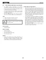
Before starting, make sure all the valves are in their
appropriate positions:
opeN
cloSeD
Hydraulic motor shutoff
Solvent flush
BPO tank / BPO shutoff
Solvent flush relief
Spray material shutoff valve
Relief valve
2.
Turn the pressure control knob fully clockwise to its
highest setting.
3.
Set the regulator on the pressurized bead tank to 30 PSI.
This is a recommended starting point. Adjust as needed.
4.
Close the BPO tank valve. This will start the flow of BPO to
the mixing block.
5.
Immediately close the relief valve located on the high
pressure filter. This will start the flow of spray material.
Attention
Spraying must take place no more than 2-3
minutes once both of these valves are closed.
Otherwise material will mix together in the
mixing block and travel to the mixing tube and
set up, rendering the system inoperable.
6.
Quickly take note of the pressure gauges on the
dashboard. Both the “A” and “B” pressure gauges should
read approximately 2000 PSI.
7.
Once it is determined that these pressures are within
approximately 100 PSI of each other, spraying can begin.
Attention
If you stop spraying for any length of time that is
more than 2-3 minutes, a solvent flush MUST BE
PERFORMED.
A solvent flush will flush out the spray mixture
from the hoses and mixing tube and keep the
spray mixture from setting up and clogging the
system. Follow the steps in the next section.
6.3
SolVeNT fluSh
Attention
Follow these steps whenever stopping spraying
for any reason. This will prevent the spray mixture
from setting up in the system and clogging it.
This solvent flush procedure also acts as a
pressure relief procedure that will relieve the
system of all pressure.
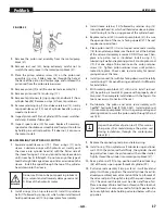
1.
Turn the pressure control knob located on the dashboard
fully counterclockwise to its lowest setting.
2.
Open the relief valve located at the high pressure filter.
This will stop the flow of spray material to the mixing block.
3.
Place a waste container underneath the spray gun(s).
4.
Turn the spray tip(s) on the spray gun(s) 180º so they face
toward the rear of the gun. This will allow the solvent flush
to easily flush through the spray guns.
5.
Set the regulator on the solvent flush tank to approximately
125 PSI.
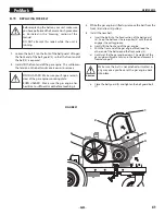
6.
Close the hydraulic motor shutoff valve (see item 11,
section 3.4).
7.
Close the BPO shutoff (blue) and spray material shutoff
(red) valves located at the mixing block (see items 6-7,
section 3.4)
8.
Immediately open the solvent flush valve. This is the valve
located opposite the mixing block as the valves closed in
step 2 (see item 5, section 3.4).
i
Solvent will start flowing from the solvent flush
tank to the mixing block, through the mixing
tube and out the spray guns.
Allow the solvent to flush though the system for
a minumum of 10 seconds, then activate the gun
10-12 times in quick succession.
Once 10 minutes has passed, close the solvent
flush valve for 2-3 minutes, and then open it
again, allowing solvent to flush through the
system for another 10 - 15 seconds.
9.
Once the system has been flushed a second time, close the
solvent flush valve.
10.
If finished spraying, the engine can be shut down.
If more spraying is to be done, follow the steps in 6.1 and
6.2 to resume spraying.
Summary of Contents for 200
Page 12: ...12 description of unit ProMark 3 3 System controls FIGURE 3 1 5 4 8 2 3 6 7 9 10 11 12 ...
Page 45: ...45 troubleshooting ProMark ...
Page 56: ...56 Gerätebeschreibung ProMark 3 3 GERÄTESTEUERUNG abb 3 1 5 4 8 2 3 6 7 9 10 11 12 ...
Page 89: ...89 ProMark ...
Page 100: ...100 Description du matériel ProMark 3 3 COMMANDES DU SYSTÈME fig 3 1 5 4 8 2 3 6 7 9 10 11 12 ...
Page 133: ...133 ProMark ...


