34
maintenance
ProMark
8.4
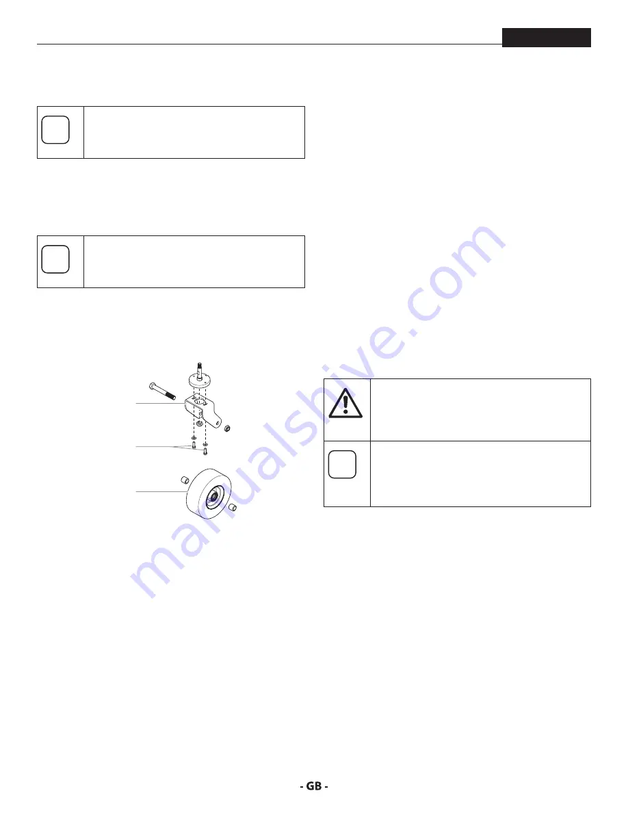
ADJuSTINg The TrAckINg of The froNT
cASTer
i
The front caster is set by the factory to track in
a straight line. Use the following procedure if
adjustment the caster becomes necessary.
1.
Loosen the two hex screws (1) in the top of the caster
mounting bracket (2).
2.
Turn the caster mounting bracket (2) slightly in the desired
direction.
i
The front caster locking pin must be engaged
during tracking adjustment.
3.
Tighten the two hex screws (1).
4.
Check the tracking of the front caster (3). If the caster does
not track straight, repeat the above procedure.
1
2
3
fIgure 21
8.5
mAINTAININg The fluID SecTIoN
If the sprayer is going to be out of service for an extended period
of time, it is recommended that following cleanup, a kerosene
and oil mixture be introduced as a preservative. Packings may
tend to dry out from lack of use. This is particularly true of the
upper packing set for which upper packing lubricant Piston
Lube (P/N 314-480) is recommended in normal usage.
If the sprayer has been out of service for an extended period
of time, it may be necessary to prime the pump with solvent.
It is extremely important that the threads on the siphon hose
coupling are properly sealed. Any air leakage will produce
erratic operation of the sprayer and may damage the system.
The up and the down strokes should be approximately equal
in time (one should not be faster than the other). A fast up or
down stroke may indicate air in the system or malfunctioning
valve or seats (see the Troubleshooting section).
8.6
hIgh-preSSure hoSe
Inspect the high-pressure hose visually for any notches or
bulges, in particular at the transition in the fittings. It must be
possible to turn the union nuts freely. A conductivity of less
than 1 MΩ must exist across the entire length.
Attention
Have all the electric tests carried by an Authorized
Titan Service Center.
i
The risk of damage rises with the age of the high-
pressure hose.
Titan recommends replacing high-pressure
hoses after 6 years.
Summary of Contents for 200
Page 12: ...12 description of unit ProMark 3 3 System controls FIGURE 3 1 5 4 8 2 3 6 7 9 10 11 12 ...
Page 45: ...45 troubleshooting ProMark ...
Page 56: ...56 Gerätebeschreibung ProMark 3 3 GERÄTESTEUERUNG abb 3 1 5 4 8 2 3 6 7 9 10 11 12 ...
Page 89: ...89 ProMark ...
Page 100: ...100 Description du matériel ProMark 3 3 COMMANDES DU SYSTÈME fig 3 1 5 4 8 2 3 6 7 9 10 11 12 ...
Page 133: ...133 ProMark ...


