38
maintenance
ProMark
13.
Thread cylinder head (8) down onto the cylinder (29) and
then back off just enough to reassemble hydraulic fittings
and motor tube (23). Tighten lock ring with spanner
wrench to hold cylinder head in position.
14.
14. The tee assembly (24) and the elbow (22) use an o-ring
(25) to seal on the outer diameter (O.D.) of the motor tube
(23). The O.D. of the motor tube should be free of scratches
or sharp edges. The lock nuts on these fittings first should
be hand tightened, then wrench tightened another half
turn.
15.
15. Install o-ring (2) onto cylinder head plug (1). Tighten.
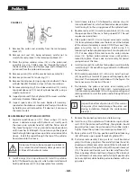
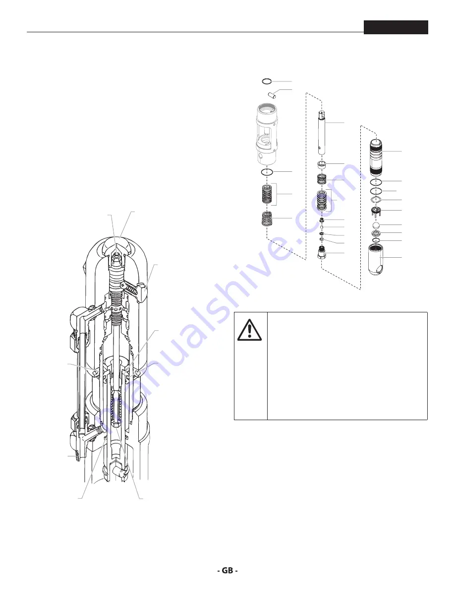
hyDrAulIc moTor cuT-AWAy
Torque flex locknut to
40 in.-lbs. (4.5 Nm).
Use blue Loctite.
Use blue
Loctite on
lock ring.
Seal lip must
face up.
Use
hydraulic
sealant.
Torque head plug to
15 ft.-lbs. (22 Nm).
Do not over-tighten
o-ring seal.
Torque trip
retainers to
8 ft.-lbs. (10.8 Nm).
Do not over-tighten
o-ring seal.
Torque piston
retainers to
40 ft.-lbs. (55 Nm).
Use red Loctite.
Seal lip must
face down.
Valve rod assembly
is factory set and
permanently Loctited.
Do not disassemble.
fIgure 24
8.9
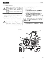
SerVIcINg The fluID SecTIoN
6
7
8
9
13
10
11
12
14
15
16
17
18
19
20
3
21
1
2
5
4
4
3
fIgure 25
Attention
Use of non-Titan service parts may void warranty.
Ask for original parts made by Titan for best
services. This pump should receive a routine
servicing after approximately 1,000 hours of use.
Earlier servicing is required if there is excessive
leakage from the top packing or if pump strokes
become faster on one stroke or the other.
The use of Titan Piston Lube (P/N 314-480) is
recommended as an upper packing lubricant.
Do not substitute oil, water, or solvent for an
upper packing lubricant.
DISASSemBlINg The fluID SecTIoN
1.
Remove the siphon hose assembly. Unthread the foot
valve housing (21) and the pump cylinder (14) with a strap
wrench.
2.
Slide the retainer ring (1) up with a small screwdriver, then
push the connecting pin (2) out.
3.
Pull the displacement rod (6) through the lower cavity of
the motor/pump block.
4.
Remove the PTFE o-ring (3), upper packing spring (5), and
upper packing set (4) from the motor/pump block.
5.
Hold the displacement rod (6) in a vise by the flats at the
top of the displacement rod and remove the outlet valve
housing (13) with a wrench while holding the displacement
Summary of Contents for 200
Page 12: ...12 description of unit ProMark 3 3 System controls FIGURE 3 1 5 4 8 2 3 6 7 9 10 11 12 ...
Page 45: ...45 troubleshooting ProMark ...
Page 56: ...56 Gerätebeschreibung ProMark 3 3 GERÄTESTEUERUNG abb 3 1 5 4 8 2 3 6 7 9 10 11 12 ...
Page 89: ...89 ProMark ...
Page 100: ...100 Description du matériel ProMark 3 3 COMMANDES DU SYSTÈME fig 3 1 5 4 8 2 3 6 7 9 10 11 12 ...
Page 133: ...133 ProMark ...


