background image

© Titan Tool Inc.  Todos los derechos reservados.

17

PELIGRO: PELIGRO DE EXPLOSIÓN DEBIDO A

MATERIALES INCOMPATIBLES  -  Podría
causar lesiones severas o daños en la
propiedad.

PARA PREVENIR:

• No utilice materiales que contengan blanqueador o cloro.
• No use solventes con hidrocarburos halogenados, tales

como productos para eliminar el moho, cloruro de
metileno y 1,1,1 - tricloroetano.  Estos no son compatibles
con el aluminio.

• Comuníquese con el proveedor del producto para obtener

información de compatibilidad con materiales de aluminio.

PELIGRO: GASES PELIGROSOS - Las pinturas, solventes,

insecticidas y otros materiales pueden ser
perjudiciales si se inhalan o entran en contacto
con el cuerpo.  Los gases pueden causar
náusea, desmayos o envenenamiento graves.

PARA PREVENIR:

• Use una mascarilla respiratoria o careta siempre que

exista la posibilidad de que se puedan inhalar vapores.
Lea todas las intrucciones que vengan con la careta para
estar seguro de que se tendrá la protección necesaria
contra la inhalación de vapores dañinos.

• Use gafas protectoras.
• Use ropa de protección, según lo requiera el fabricante

del producto.

PELIGRO: GENERAL - Puede causar daños en la

propiedad o lesiones severas.

PARA PREVENIR:

• Lea todas las instrucciones y advertencias de seguridad

antes de hacer funcionar cualquier equipo.

• Desconecte siempre el motor del suministro eléctrico

antes de dar servicio al equipo.

• Observe todos los códigos locales, estatales y nacionales

apropiados que rigen las medidas de ventilación,
prevención de incendios y operación. 

• Los Estándares de Seguridad del Gobierno de los

Estados Unidos se han adoptado bajo el Acta de
Seguridad y Salud Ocupacionales (OSHA por sus siglas
en inglés). Deben consultarse estos estándares,
particularmente la parte 1910 de los Estándares
Generales y la parte 1926 de los Estándares de la
Construcción.

• Utilice únicamente piezas autorizadas por el fabricante.

El usuario asume todos los riesgos y responsabilidades si
usa piezas que no cumplen con las especificaciones
mínimas y dispositivos de seguridad del fabricante de la
bomba.

• Antes de usarla cada vez, revise todas las mangueras para

ver que no tengan cortadas, fugas, una cubierta desgastada
por abrasión o con abolladuras, así como uniones dañadas
o que se hayan movido. Si existiera cualquiera de estas
condiciones, reemplace la manguera inmediatamente. No
repare nunca una manguera de pintura. Reemplácela con
otra manguera conectada a tierra.

• Todas las mangueras, soportes giratorios, pistolas y

accesorios que se usen con esta unidad deben tener una
capacidad de presión de 3200 lb/pulg2 / 221 BAR o
mayor.

• No atomice en días con viento.
• Use ropa que evite el contacto de la pintura con la piel y

el cabello.

Instrucciones para conectar a tierra

Este producto se debe conectar a tierra.  En caso de que
ocurra un corto circuito, la conexión a tierra reduce el riesgo
de choque eléctrico al proporcionar un alambre de escape
para la corriente eléctrica.  Este producto está equipado con
un cable que tiene un alambre de conexión a tierra con un
enchufe de conexión a tierra apropiado.  El enchufe se debe
enchufar en una toma de corriente que se haya instalado y
conectado a tierra debidamente, de acuerdo con todos los
códigos y estatutos locales.

PELIGRO — 

Una instalación inapropiada del enchufe de

conexión a tierra puede dar como resultado el que exista un
riesgo de choque eléctrico. Si es necesario reparar o
reemplazar el cable o el enchufe, no conecte el alambre de
conexión a tierra a ninguno de los terminales de hoja planos.
El alambre con aislamiento que tiene la superficie exterior de
color verde con franjas amarillas o sin ellas es el alambre de
conexión a tierra que debe conectarse al conector de conexión
a tierra.

Verifique con un electricista o técnico de servicio calificado si
las instrucciones para conectar a tierra no le han quedado
completamente claras, o si duda que el producto haya
quedado conectado a tierra de manera apropiada.  No
modifique el enchufe que se proporciona.  Si el enchufe no
entra en la toma de corriente, pídale a un electricista calificado
que instale la toma apropiada.
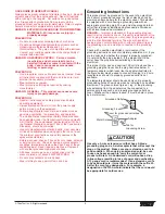
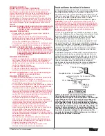
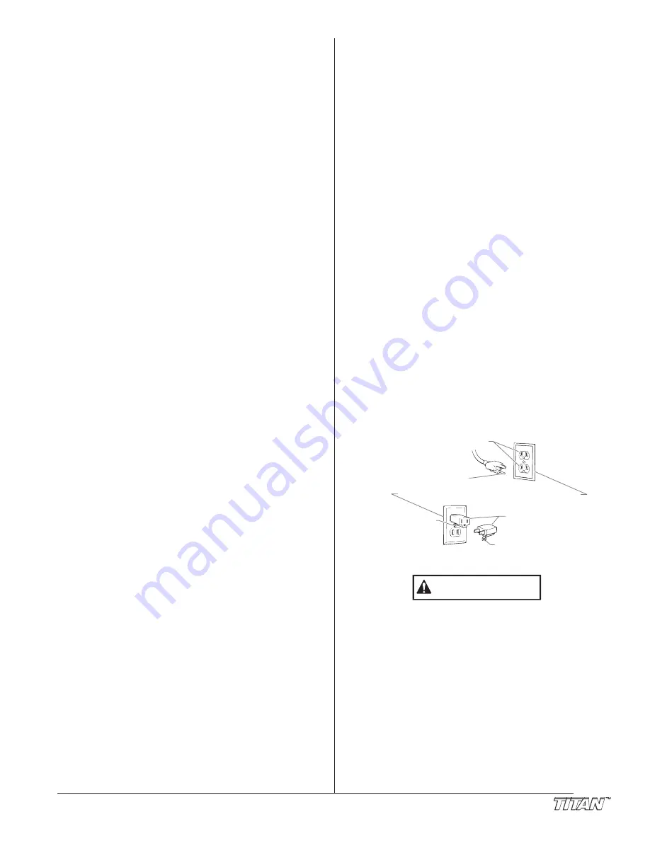
Este producto está diseñado para usarse en un circuito de 120
voltios nominales y el enchufe de conexión a tierra que tiene
se parece al enchufe que se ilustra a continuación.  Si no
dispone de una toma de corriente con conexión a tierra, puede
usar un adaptador temporal que se asemeja al adaptador
ilustrado en la figura a continuación, para conectar este
enchufe en un receptáculo de 2 polos como se muestra.
El adaptador temporal solamente se debe utilizar hasta que un
electricista calificado instale debidamente una toma de
corriente con conexión a tierra. La patilla verde o alambre de
conexión a tierra que se extiende desde el adaptador se debe
conectar a tierra permanente, tal como la tapa de una caja de
distribución conectada a tierra. Cuando use el adaptador, debe
mantenerlo en su lugar con un tornillo metálico.

Use solamente extensiones trifilares que tengan un
enchufe de conexión a tierra de 3 hojas y un receptáculo
de triple ranura que acepte el enchufe del producto.
Asegúrese de que su extensión esté en buenas
condiciones.  Cuando use una extensión, asegúrese de
usar una que sea lo suficientemente resistente como para
soportar la corriente que descargue su producto.  Un
cable de un tamaño menor causará una caída de voltage
en la línea que dará como resultado una pérdida de
energía y un sobrecalenta|ôento.  Se recomienda usar un
cable de calibre 12.  Si se utiliza un cable de extensión en
el exterior, tiene que estar marcado con el sufijo W-A
después de la designación del tipo de cable.  Por ejemplo,
SJTW-A para indicar que el cable es apropiado para uso
en exteriores.

PRECAUCION

Tomacorriente aterrado

Terminal de tierra

Lengueta
del tornillo
de conexi n a tierra

Adaptador

Tornillo met lico

Tapa de la caja del tomacorriente aterrado

Summary of Contents for 330

Page 1: ...ns important warnings and instructions Please read and retain for reference Do not use this equipment before reading this manual 330 Airless Sprayer NOTE This manual contains important warnings and instructions Please read and retain for reference Model Numbers 110V Complete 704 2000 110V Bare 704 2010 230V Complete 704 2030 CE 110V Complete 704 2000 CE ...

Page 2: ...rayer manual ALWAYS keep the tip guard in place while spraying The tip guard provides some protection but is mainly a warning device ALWAYS remove the spray tip before flushing or cleaning the system The paint hose can develop leaks from wear kinking and abuse A leak can inject material into the skin Inspect the hose before each use NEVER use a spray gun without a trigger lock and trigger guard in...

Page 3: ...kin and hair Grounding Instructions This product must be grounded In the event of an electrical short circuit grounding reduces the risk of electric shock by providing an escape wire for the electric current This product is equipped with a cord having a grounding wire with an appropriate grounding plug The plug must be plugged into an outlet that is properly installed and grounded in accordance wi...

Page 4: ...he system 1 Place the suction tube into a container of mineral spirits 2 Place the return hose into a metal waste container 3 Turn the pressure control knob fully counterclockwise to its lowest pressure setting 4 Move the PRIME SPRAY valve down to the PRIME position 5 Turn the unit on by moving the ON OFF switch to the ON position 6 Slowly turn the pressure control knob clockwise to increase the p...

Page 5: ... Trigger lock in locked position WARNING 11 Unlock the gun by turning the gun trigger lock to the unlocked position Ground the gun by holding it against the edge of the metal container while flushing Failure to do so may lead to a static electric discharge which may cause a fire 12 Trigger the gun into the metal waste container until all air and solvent is flushed from the spray hose and paint is ...

Page 6: ...e start stroke release trigger pull trigger end stroke WARNING 6 Titan Tool Inc All rights reserved For corners and edges split the center of the spray pattern on the corner or edge and spray vertically so that both adjoining sections receive approximately even amounts of paint If conditions are windy angle the spray pattern into the wind to minimize drifting Work from ground to roof Do not attemp...

Page 7: ...ming out of the gun is clean NOTE Pulling and releasing the trigger of the spray gun creates a pulsing action that cleans out the hose and the spray gun more effectively WARNING WARNING CAUTION WARNING 14 Follow the Pressure Relief Procedure found in the Operation section of this manual 15 Unplug the unit and store in a clean dry area Do not store the unit under pressure Maintenance Before proceed...

Page 8: ...sher Cover Plate Brush Clamp Rear Bearing Housing Pump Housing Armature Motor Wires 8 Titan Tool Inc All rights reserved Replacing the Motor Brushes 1 Loosen and remove the rear cover screws Remove the rear cover 2 Loosen and remove the end cap screws Remove the end cap 3 Loosen and remove the brush clamp screws Remove the brush clamps 4 Disconnect the wire lead to the motor brushes Remove the mot...

Page 9: ...ble the pump by reversing steps 1 3 Refer to the electrical schematic in the Parts List section of this manual for proper wiring of the pressure switch NOTE After installation the pressure may need to calibrated by an authorized Titan service center Motor Starter Pressure Switch Bracket NOTE Always use heat sink material on the back of the motor starter WARNING Replacing the Switch Stem 1 Remove t...

Page 10: ...er Cage Lower Seal WARNING 10 Titan Tool Inc All rights reserved Repacking the Fluid Section 1 Remove the foot valve and outlet valve assemblies using the steps in the Servicing the Valves procedure above 2 Using 3 8 and 5 32 hex wrenches loosen and remove the three pump block mounting screws 3 Pull the pump block down approximately 1 2 from the pump housing 4 Slide the pump block and piston rod f...

Page 11: ...teps 1 6 T Slot Pump Housing Pump Block Gasket Transducer Front Cover NOTE Make sure the o ring is in position on the transducer before threading it into the main assembly housing Also make sure the gasket is in position in the pump block WARNING NOTE Repacking kit P N 704 113 is available For best results use all parts supplied in this kit Replacing the Filters Pump Filter 1 Loosen and remove the...

Page 12: ...e in pump blown 1 Air in line 2 Insufficient pressure 1 No paint 2 Siphon strainer clogged 3 Pump gun filter clogged 4 Sprayer will not prime material too heavy 1 Air leak in system 2 Air leak in siphon tube 3 Inlet valve not seating 4 Worn packings 5 Dirty or worn ball valves 6 Worn valve seats 7 Worn prime valve 1 Pressure setting too low 2 Plugged filters 3 Spray tip too big or worn 1 Wrong typ...

Page 13: ...velocity 4 Material too cohesive 5 Tip worn past pump capacity 1 Worn tip 2 Tip may be chipped 1 Plugged worn or chipped tip 1 Leak in suction tube 2 Not enough hose 3 Tip too large or worn Solution 1 Increase pressure 2 Change to smaller tip 3 Clean gun and pump filters 4 Reduce viscosity 5 Replace 1 Replace 2 Replace 1 Clean or replace 1 Tighten 2 Use a minimum of 50 15m of 1 4 high pressure hos...

Page 14: ...NTION AVERTISSEMENT DANGER RISQUES D EXPLOSION OU D INCENDIE Les vapeurs dégagées par le solvant ou la peinture sont explosives et inflammables et peuvent causer des corporels sérieux ou dommages matériels MESURES PRÉVENTIVES Veiller à éviter toute accumulation de vapeurs inflammables en vous assurant que la zone où la pulvérisation a lieu est suffisamment ventilée Veiller à éviter la présence de ...

Page 15: ...ble d alimentation en peinture Le remplacer par un autre flexible mis à la terre Tout flexible raccord orientable pistolet et accessoire utilisé avec cet appareil doit pouvoir fonctionner à une pression égale ou supérieure à 3 200 lb po2 221BAR Ne jamais pulvériser lorsqu il vente Porter des vêtements pour protéger la peau et les cheveux contre tout contact avec la peinture Instructions de mise à ...

Page 16: ...REVENIR Debe proveerse un escape y aire fresco para hacer que el aire que está dentro del área de atomización se mantenga libre de acumulaciones de vapores inflamables Evite todas las fuentes de ignición como son las chispas electrostáticas llamas abiertas flamas de piloto objetos calientes cigarros y chispas que se generan al conectar y desconectar las extensiones o de apagadores de luz que estén...

Page 17: ...a reduce el riesgo de choque eléctrico al proporcionar un alambre de escape para la corriente eléctrica Este producto está equipado con un cable que tiene un alambre de conexión a tierra con un enchufe de conexión a tierra apropiado El enchufe se debe enchufar en una toma de corriente que se haya instalado y conectado a tierra debidamente de acuerdo con todos los códigos y estatutos locales PELIGR...

Page 18: ...18 Titan Tool Inc All rights reserved Parts List Main Assembly ...

Page 19: ...V units Item Part Description Quantity 7 700 766 Screw 8 32 UN x 1 125 4 8 Motor housing and field 1 9 700 640 Spring washer 1 10 Armature 1 11 700 070 Motor kit complete includes items 3 4 5 6 8 9 10 1 700 084 Motor kit complete 230V units Stand Assembly Item Part Description Quantity 1 765 126 Screw 4 2 700 674 End cap 4 3 704 092 Leg left includes items 2 and 4 1 4 700 781 Drip cup 1 5 700 069 ...

Page 20: ...20 Titan Tool Inc All rights reserved Gear Box Assembly 5 1 2 3 4 6 7 8 9 10 11 20 21 22 23 24 25 26 27 28 29 30 31 32 12 13 14 15 33 34 36 37 40 38 39 35 17 18 16 19 ...

Page 21: ...ressure switch 1 30 704 130 Insulator plate 1 31 704 104 Bracket 1 32 765 054 Power cord 1 700 280 Power cord 230V units 200 209 Power cord 110V units 33 704 102 Pressure control knob 1 34 704 123 Spring 1 35 704 114 Switch stem includes item 36 1 36 761 207 O ring 1 37 704 124 Snap ring 1 38 704 125 Washer 2 39 704 126 Lockwasher 2 40 700 139 Screw 2 41 700 191 In line fuse 230v units only 1 42 7...

Page 22: ...E SPRAY valve assembly Includes items 9 19 1 9 700 537 Gasket 1 10 221 012 O ring Viton 1 11 222 012 O ring PTFE 1 Item Part Description Quantity 12 700 246 Valve housing 1 13 700 721 O ring Viton 1 700 897 O ring PTFE optional 1 14 700 250 Valve stem 1 15 700 244 Spring 1 16 700 248 Valve retainer 1 17 700 252 Cam base 1 18 700 697 Valve handle 1 19 700 759 Groove pin 1 NOTE When using HOT solven...

Page 23: ...election is determined by the fan width required for a specific job and by the orifice size that will supply the desired amount of fluid and accomplish proper atomization For light viscosity fluids smaller orifice tips generally are desired For heavier viscosity materials larger orifice tips are preferred Please refer to the chart below The following chart indicates the most common sizes and the a...

Page 24: ...aid by the End User Repaired or replaced equipment will be returned to the End User transportation prepaid THERE IS NO OTHER EXPRESS WARRANTY TITAN HEREBY DISCLAIMS ANY AND ALL IMPLIED WARRANTIES INCLUDING BUT NOT LIMITED TO THOSE OF MERCHANTABILITY AND FITNESS FOR A PARTICULAR PURPOSE TO THE EXTENT PERMITTED BY LAW THE DURATION OF ANY IMPLIED WARRANTIES WHICH CANNOT BE DISCLAIMED IS LIMITED TO TH...

Reviews: